
Datasheet


MAX5895
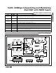
16-Bit, 500Msps Interpolating and Modulating
Dual DAC with CMOS Inputs
______________________________________________________________________________________ 19
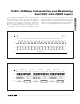
The MAX5895 can be configured to latch the input
data on either the rising edge or falling edge of the
DATACLK signal (bit 4, address 02h). Figure 4 shows
the timing requirements between the DATACLK signal
and the input data bus with latching on the rising edge.
Interpolating Filter
The MAX5895 features three cascaded FIR half-band
filters. The interpolating filters are enabled or disabled
in combinations to support 1x (no interpolation), 2x, 4x,
or 8x interpolation. Bits 7 and 6 of register 01h set the
interpolation rate (see Table 2). The last interpolation fil-
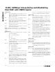
Figure 5. Interpolation Filter Frequency Response, 2x
Interpolation Mode
0 0.1 0.2 0.3 0.4
-0.0004
-0.0002
0
PASSBAND DETAIL
0
0 0.4 0.6 0.8
f
OUT
- NORMALIZED TO INPUT DATA RATE
1.0 1.2 1.4 1.6 1.8 2.0
-20
-40
-60
-80
-100
GAIN (dBFS)
-120
0.2
0 0.1 0.2 0.3
0.4
-0.0004
-0.0002
0
PASSBAND DETAIL
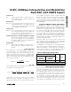
Figure 6. Interpolation Filter Frequency Response, 4x
Interpolation Mode
0
0 1.0 1.5 2.0
f
OUT
- NORMALIZED TO INPUT DATA RATE
2.5 3.0 3.5 4.0
-20
-40
-60
-80
-100
GAIN (dBFS)
-120
0.5
0 0.1 0.2 0.3 0.4
-0.0004
-0.0002
0
PASSBAND DETAIL
Figure 7. Interpolation Filter Frequency Response, 8x
Interpolation Mode (FIR3 Lowpass Mode)
0
0234
f
OUT
- NORMALIZED TO INPUT DATA RATE
5678
-20
-40
-60
-80
-100
GAIN (dBFS)
-120
1
0 0.1 0.2 0.3 0.4
-0.0004
-0.0002
0
PASSBAND DETAIL
Figure 8. Interpolation Filter Frequency Response, 8x
Interpolation Mode (FIR3 Highpass Mode)
0
0234
f
OUT
- NORMALIZED TO INPUT DATA RATE
5678
-20
-40
-60
-80
-100
GAIN (dBFS)
-120
1
3.6 3.8 4.0 4.2 4.4
-0.0004
-0.0002
0
PASSBAND DETAIL