
Datasheet
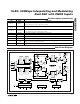


MAX5895
16-Bit, 500Msps Interpolating and Modulating
Dual DAC with CMOS Inputs
16 ______________________________________________________________________________________
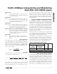
Address 00h
Bit 6 Logic 0 (default) causes the serial port to use
MSB first address/data format. When set to a
logic 1, the serial port will use LSB first
address/data format.
Bit 5 When set to a logic 1, all registers reset to
their default state (this bit included).
Bit 4 Logic 1 stops the clock to the digital interpo-
lators. DAC outputs hold last value prior to
interpolator power-down.
Bit 3 IDAC power-down mode. A logic 1 to this bit
powers down the IDAC.
Bit 2 QDAC power-down mode. A logic 1 to this bit
powers down the QDAC.
Note: If both bit 2 and bit 3 are 1, the MAX5895 is in
full-power-down mode, leaving only the serial interface
active.
Address 01h
Bits 7, 6 Configure the interpolation filters according
to the following table:
00 1x (no interpolation)
01 2x
10 4x
11 8x (default)
Bit 5 Logic 0 configures FIR3 as a lowpass digital
filter (default). A logic 1 configures FIR3 as a
highpass digital filter.
Bits 4, 3 Configure the modulation frequency accord-
ing to the following table:
00 No modulation
01 f
IM
/2 modulation
10 f
IM
/4 modulation (default)
11 f
IM
/4 modulation
where f
IM
is the data rate at the input of the
modulator.
Bit 2 Configures the modulation mode for either
real or complex (image reject) modulation.
Logic 1 sets the modulator to the real mode
(default). Complex modulation is only avail-
able for f
IM
/4 modulation.
Bit 1 Quadrature modulator sign inversion. With I-
channel data leading Q-channel data by 90°,
logic 0 sets the complex modulation to be
e
-jw
(default), cancelling the upper image
when used with an external quadrature mod-
ulator. A logic 1 sets the complex modulation
to be e
+jw
, cancelling the lower image when
used with an external quadrature modulator.
Address 02h
Bit 7 Logic 0 (default) configures the data port for
two’s complement. A logic 1 configures the
data ports for offset binary.
Bit 6 Logic 0 (default) configures the data bus for
single-port, interleaved I/Q data. I and Q data
enter through one 16-bit bus. Logic 1 config-
ures the data bus for dual-port I/Q data. I and
Q data enter on separate buses.
Bit 5 Logic 0 (default) configures the data clock
for pin 14. A logic 1 configures the data clock
for pin 27 (DATACLK/B14).
Bit 4 Logic 0 (default) sets the internal latches to
latch the data on the rising edge of DATACLK.
A logic 1 sets the internal latches to latch the
data on the falling edge of DATACLK.
Bit 3 Logic 0 (default) configures the DATACLK
pin (pin 14 or pin 27) to be an input. A logic 1
configures the DATACLK pin to be an output.
Bit 2 Logic 0 (default) enables the data synchro-
nizer circuitry. A logic 1 disables the data
synchronizer circuitry.
Address 03h
Bits 7–0 Unused.
Address 04h
Bits 7–0 These 8 bits define the binary number for
fine-gain adjustment of the IDAC full-scale
current (see the
Gain Adjustment
section). Bit
7 is the MSB. Default is all zeros.
Address 05h
Bits 3–0 These four bits define the binary number for
the coarse-gain adjustment of the IDAC full-
scale current (see the
Gain Adjustment
sec-
tion). Bit 3 is the MSB. Default is all ones.
Address 06h, Bits 7 to 0; Address 07h, Bit 1 and Bit 0
These 10 bits represent a binary number that
defines the magnitude of the offset added to
the IDAC output (see the
Offset Adjustment
section). Default is all zeros.