
Datasheet


MAX5895
16-Bit, 500Msps Interpolating and Modulating
Dual DAC with CMOS Inputs
12 ______________________________________________________________________________________
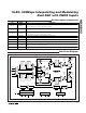
Detailed Description
The MAX5895 dual, 500Msps, high-speed, 16-bit, cur-
rent-output DAC provides superior performance in
communication systems requiring low-distortion ana-
log-signal reconstruction. The MAX5895 combines two
DAC cores with 8x/4x/2x/1x programmable digital inter-
polation filters, a digital quadrature modulator, an SPI-
compatible serial interface for programming the device,
and an on-chip 1.20V reference. The full-scale output
current range is programmable from 2mA to 20mA to
optimize power dissipation and gain control.
Each channel contains three selectable interpolating fil-
ters making the MAX5895 capable of 1x, 2x, 4x, or 8x
interpolation, which allows for low-input and high-out-
put data rates. When operating in 8x interpolation
mode, the interpolator increases the DAC conversion
rate by a factor of eight, providing an eight-fold
increase in separation between the reconstructed
waveform spectrum and its first image. The MAX5895
accepts either two’s complement or offset binary input
data format and can operate from either a single- or
dual-port input bus.
The MAX5895 includes modulation modes at f
IM
/2 and
f
IM
/4, where f
IM
is the data rate at the input of the modula-
tor. If 2x interpolation is used, this data rate is 2x the input
data rate. If 4x or 8x interpolation is used, this data rate is
4x the input data rate. Table 1 summarizes the modulator
operating data rates for dual-port mode.
The power-down modes can be used to turn off each
DAC’s output current or the entire digital section.
Programming both DACs into power-down simultane-
ously will automatically power down the digital interpo-
lator filters. Note the SPI section is always active.
The analog and digital sections of the MAX5895 have
separate power-supply inputs (AV
DD3.3
, AV
DD1.8
,
AV
CLK
, DV
DD3.3
, and DV
DD1.8
), which minimize noise
coupling from one supply to the other. AV
DD1.8
and
DV
DD1.8
operate from a typical 1.8V supply, and all
other supply inputs operate from a typical 3.3V supply.
Serial Interface
The SPI-compatible serial interface programs the
MAX5895 registers. The serial interface consists of the
CS, SDI, SCLK, and SDO. Data is shifted into SDI on
the rising edge of the SCLK when CS is low. When CS
is high, data presented at SDI is ignored and SDO is in
high-impedance mode. Note: CS must transition high
after each read/write operation. SDO is the serial data
output for reading registers to facilitate easy debug-
ging during development. SDI and SDO can be con-
nected together to form a 3-wire serial interface bus or
remain separate and form a 4-wire SPI bus.
The serial interface supports two-byte transfer in a
communication cycle. The first byte is a control byte
written to the MAX5895 only. The second byte is a data
byte and can be written to or read from the MAX5895.
Table 1. Quadrature Modulator Operating Data Rates (f
IM
is the Data Rate at the Input of
the Modulator) for Dual-Port Mode
INTERPOLATION RATE MODULATION MODE (f
LO
)
MODULATION FREQUENCY
RELATIVE TO f
DAC
MODULATION FREQUENCY
RELATIVE TO f
DATA
f
IM
/2 f
DAC
/2 f
DATA
/2
1x
f
IM
/4 f
DAC
/4 f
DATA
/4
f
IM
/2 f
DAC
/2 f
DATA
2x
f
IM
/4 f
DAC
/4 f
DATA
/2
f
IM
/2 f
DAC
/2 2 x f
DATA
4x
f
IM
/4 f
DAC
/4 f
DATA
f
IM
/2 f
DAC
/4 2 x f
DATA
8x
f
IM
/4 f
DAC
/8 f
DATA