
Datasheet


MAX5895
16-Bit, 500Msps Interpolating and Modulating
Dual DAC with CMOS Inputs
______________________________________________________________________________________ 11
Pin Description (continued)
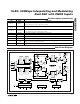
Functional Diagram
PIN NAME FUNCTION
53, 67 AV
DD1.8
Low Analog Power Supply. Accepts a 1.71V to 1.89V supply range. Bypass each pin to GND with
a 0.1µF capacitor as close to the pin as possible.
54, 56, 59, 61,
64, 66
GND Ground
55, 60, 65 AV
DD3.3
Analog Power Supply. Accepts a 3.135V to 3.465V supply range. Bypass each pin to GND with a
0.1µF capacitor as close to the pin as possible.
57 OUTQN Inverting Differential DAC Current Output for Q-Channel
58 OUTQP Noninverting Differential DAC Current Output for Q-Channel
62 OUTIN Inverting Differential DAC Current Output for I-Channel
63 OUTIP Noninverting Differential DAC Current Output for I-Channel
68 AV
CLK
Clock Power Supply. Accepts a 3.135V to 3.465V supply range. Bypass to ground with a 0.1µF
capacitor as close to the pin as possible.
— EP Exposed Pad. Must be connected to GND through a low-impedance path.
IDAC
OUTIP
OUTIN
QDAC
OUTQP
OUTQN
SELIQ
A0–A15
B0–B15
DATACLK
SERIAL INTERFACE
CONTROL REGISTERS
REFERENCE
MODULATOR
CLOCK BUFFERS
AND DIVIDERS
CLKPCLKN
RESET
f
CLK
f
DAC
f
DAC
DATA SYNCH
AND DEMUX
MUX
Q
I
Q
I
2x
INTERPOLATING
FILTER
2x
INTERPOLATING
FILTER
2x
INTERPOLATING
FILTER
2x
INTERPOLATING
FILTER
2x
INTERPOLATING
FILTER
2x
INTERPOLATING
FILTER
MUX
MUX
MUX
DIGITAL
OFFSET
ADJUST
DIGITAL
OFFSET
ADJUST
DIGITAL
GAIN
ADJUST
/2/2
SDO SDI CS SCLK DACREF FSADJ REFIO
∑
∑
∑
f
IM
/2, f
IM
/4
∑
DIGITAL
GAIN
ADJUST
/2/2
MAX5895