
Datasheet


MAX5894
14-Bit, 500Msps, Interpolating and Modulating
Dual DAC with CMOS Inputs
______________________________________________________________________________________ 19
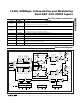
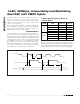
Interpolating Filter
The MAX5894 features three cascaded FIR half-band
filters. The interpolating filters are enabled or disabled
in combinations to support 1x (no interpolation), 2x, 4x,
or 8x interpolation. Bits 7 and 6 of register 01h set the
interpolation rate (see Table 2). The last interpolation fil-
ter is located after the modulator. In the 8x interpolation
mode, the last filter (FIR3) can be configured as low-
pass or highpass (bit 5, address 01h) to select the
lower or upper sideband from the modulation output.
The frequency responses of these three filters are plot-
ted in Figures 5–8.
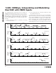
Figure 5. Interpolation Filter Frequency Response, 2x
Interpolation Mode
0 0.1 0.2 0.3 0.4
-0.0004
-0.0002
0
PASSBAND DETAIL
0
0 0.4 0.6 0.8
f
OUT
- NORMALIZED TO INPUT DATA RATE
1.0 1.2 1.4 1.6 1.8 2.0
-20
-40
-60
-80
-100
GAIN (dBFS)
-120
0.2
0
0.1
0.2
0.3
0.4
-0.0004
-0.0002
0
PASSBAND DETAIL
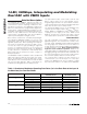
Figure 6. Interpolation Filter Frequency Response, 4x
Interpolation Mode
0
0 1.0 1.5 2.0
f
OUT
- NORMALIZED TO INPUT DATA RATE
2.5 3.0 3.5 4.0
-20
-40
-60
-80
-100
GAIN (dBFS)
-120
0.5
0
0.1
0.2
0.3
0.4
-0.0004
-0.0002
0
PASSBAND DETAIL
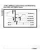
Figure 7. Interpolation Filter Frequency Response, 8x
Interpolation Mode (FIR3 Lowpass Mode)
0
0234
f
OUT
- NORMALIZED TO INPUT DATA RATE
5678
-20
-40
-60
-80
-100
GAIN (dBFS)
-120
1
0
0.1
0.2
0.3
0.4
-0.0004
-0.0002
0
PASSBAND DETAIL
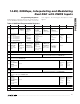
Figure 8. Interpolation Filter Frequency Response, 8x
Interpolation Mode (FIR3 Highpass Mode)
0
0234
f
OUT
- NORMALIZED TO INPUT DATA RATE
5678
-20
-40
-60
-80
-100
GAIN (dBFS)
-120
1
3.6 3.8 4.0 4.2 4.4
-0.0004
-0.0002
0
PASSBAND DETAIL