
Datasheet


MAX5873
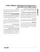
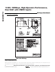
12-Bit, 200Msps, High-Dynamic-Performance,
Dual DAC with CMOS Inputs
______________________________________________________________________________________ 11
CMOS-Compatible Digital Inputs
Input Data Format Select (TORB,
DORI
)
The TORB input selects between two’s-complement or
binary digital input data. Set TORB to a CMOS-logic-
high level to indicate a two’s-complement input format.
Set TORB to a CMOS-logic-low level to indicate a bina-
ry input format.
The DORI input selects between a dual-port (parallel) or
single-port (interleaved) DAC. Set DORI high to configure
the MAX5873 as a dual-port DAC. Set DORI low to con-
figure the MAX5873 as a single-port DAC. In dual-port
mode, connect SELIQ to ground.
CMOS DAC Inputs (A11/B11–A0/B0, XOR, SELIQ)
The MAX5873 latches input data on the rising edge of
the clock in a user-selectable two’s-complement or bina-
ry format. A logic-high voltage on TORB selects two’s-
complement and a logic-low selects offset binary format.
The MAX5873 includes a single-ended, CMOS-compati-
ble XOR input. Input data (all bits) are compared with the
bit applied to XOR through exclusive-OR gates. Pulling
XOR high inverts the input data. Pulling XOR low leaves
the input data noninverted. By applying a previously
encoded pseudo-random bit stream to the data input and
applying decoding to XOR, the digital input data can be
decorrelated from the DAC output, allowing for the trou-
bleshooting of possible spurious or harmonic distortion
degradation due to digital feedthrough on the printed
circuit board (PCB).
A11/B11–A0/B0, XOR, and SELIQ are latched on the ris-
ing edge of the clock. In single-port mode (DORI pulled
low) a logic-high signal on SELIQ directs the B11–B0
data onto the I-DAC inputs. A logic-low signal at SELIQ
directs data to the Q-DAC inputs. In dual-port (parallel)
mode (DORI pulled high), data on pins A11–A0 are
directed onto the Q-DAC inputs and B11–B0 are directed
onto the I-DAC inputs.
Power-Down Operation (PD)
The MAX5873 also features an active-high power-down
mode that reduces the DAC’s digital current consumption
from 21.5mA to less than 2µA and the analog current
consumption from 76mA to less than 2µA. Set PD high
to power down the MAX5873. Set PD low for normal
operation.
When powered down, the MAX5873 reduces the overall
power consumption to less than 14µW. The MAX5873
requires 10ms to wake up from power-down and enter
a fully operational state. The PD integrated pulldown
resistor activates the MAX5873 if PD is left floating.
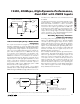
OUTIP
OUTIN
1.2V
REFERENCE
CURRENT-SOURCE
ARRAY DAC
REFIO
FSADJ
R
SET
I
REF
10kΩ
DACREF
1µF
I
REF
= V
REFIO
/ R
SET
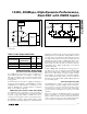
Figure 2. Reference Architecture, Internal Reference
Configuration
I
OUT
I
OUT
OUTIN OUTIP
CURRENT
SOURCES
CURRENT
SWITCHES
AV
DD
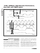
Figure 3. Simplified Analog Output Structure
DIGITAL INPUT CODE
OFFSET BINARY
TWO’S
COMPLEMENT
OUT_P OUT_N
0000 0000 0000 1000 0000 0000 0 I
OUTFS
0111 1111 1111 0000 0000 0000 I
OUTFS
/ 2 I
OUTFS
/ 2
1111 1111 1111 0111 1111 1111 I
OUTFS
0
Table 2. DAC Output Code Table