
Datasheet


MAX5864
Ultra-Low-Power, High Dynamic-
Performance, 22Msps Analog Front End
_______________________________________________________________________________________ 7
ELECTRICAL CHARACTERISTICS (continued)
(V
DD
= 3V, OV
DD
= 1.8V, internal reference (1.024V), C
L
≈ 10pF on all digital outputs, f
CLK
= 22MHz, ADC input amplitude = -0.5dBFS,
DAC output amplitude = 0dBFS, differential ADC input, differential DAC output, C
REFP
= C
REFN
= C
COM
= 0.33µF, Xcvr mode, unless
otherwise noted. Typical values are at T
A
= +25°C, unless otherwise noted.) (Note 1)
PARAMETER
SYMBOL
CONDITIONS
MIN
TYP
MAX
UNITS
Input Low Threshold V
INL
DD0–DD9, CLK, SCLK, DIN, CS
0.3 x
OV
DD
V
Input Leakage DI
IN
DD0–DD9, CLK, SCLK, DIN, CS = OGND or
OV
DD
±5µA
Input Capacitance DC
IN
5pF
DIGITAL OUTPUTS (DA0–DA7)
Output Voltage Low V
OL
I
SINK
= 200µA
0.2 x
OV
DD
V
Output Voltage High V
OH
I
SOURCE
= 200µA
0.8 x
OV
DD
V
Tri-State Leakage Current I
LEAK
±5µA
Tri-State Output Capacitance C
OUT
5pF
Note 1: Specifications from T
A
= +25°C to +85°C are guaranteed by product tests. Specifications from T
A
= +25°C to -40°C are
guaranteed by design and characterization.
Note 2: The minimum clock frequency for the MAX5864 is 7.5MHz.
Note 3: SNR, SINAD, SFDR, HD3, and THD are based on a differential analog input voltage of -0.5dBFS referenced to the amplitude
of the digital outputs. SINAD and THD are calculated using HD2 through HD6.
Note 4: Guaranteed by design and characterization.
Note 5: Crosstalk rejection is measured by applying a high-frequency test tone to one channel and a low-frequency tone to the sec-
ond channel. FFTs are performed on each channel. The parameter is specified as the power ratio of the first and second
channel FFT test tone bins.
Note 6: Amplitude/phase matching is measured by applying the same signal to each channel, and comparing the magnitude and
phase of the fundamental bin on the calculated FFT.
Typical Operating Characteristics
(V
DD
= DV
DD
= 3V, OV
DD
= 1.8V, internal reference (1.024V), C
L
≈ 10pF on all digital outputs, f
CLK
= 22MHz 50% duty cycle, ADC
input amplitude = -0.5dBFS, DAC output amplitude = 0dBFS, differential ADC input, differential DAC output, C
REFP
= C
REFN
=
C
COM
= 0.33µF, Xcvr mode, T
A
= +25°C, unless otherwise noted.)
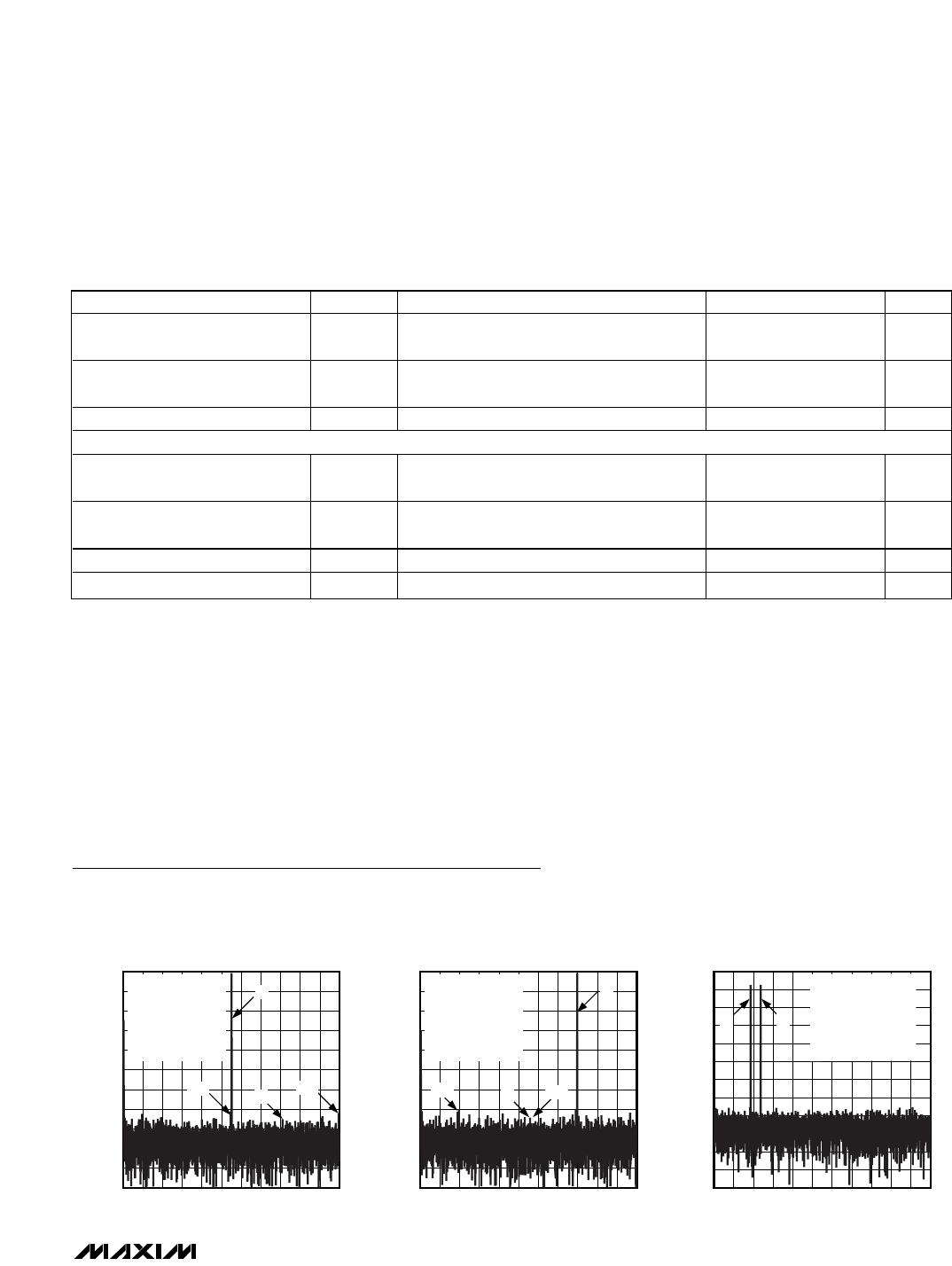
ADC CHANNEL-IA FFT PLOT
MAX5864 toc01
FREQUENCY (MHz)
AMPLITUDE (dBFS)
1097 82 3 4 5 61
-100
-90
-80
-70
-60
-50
-40
-30
-20
-10
0
-110
011
f
CLK
= 22MHz
f
IA
= 5.50885MHz
f
QA
= 7.9787MHz
A
IA
= A
QA
= -0.5dBFS
8192-POINT
DATA RECORD
HD3
HD2
IA
QA
ADC CHANNEL-QA FFT PLOT
MAX5864 toc02
FREQUENCY (MHz)
AMPLITUDE (dBFS)
1097 82 3 4 5 61
-100
-90
-80
-70
-60
-50
-40
-30
-20
-10
0
-110
011
f
CLK
= 22MHz
f
IA
= 5.50885MHz
f
QA
= 7.9787MHz
A
IA
= A
QA
= -0.5dBFS
8192-POINT
DATA RECORD
HD3
HD2
QA
IA
-110
-100
-90
-80
-70
-60
-50
-40
-30
-20
-10
0
-120
ADC CHANNEL-IA TWO-TONE FFT PLOT
MAX5864 toc03
FREQUENCY (MHz)
AMPLITUDE (dBFS)
10978234561011
f
CLK
= 22MHz
f
1
= 1.8MHz
f
2
= 2.2MHz
A
IA =
-7dBFS PER TONE
8192-POINT
DATA RECORD
F
2
F
1