
Datasheet


MAX5864
Ultra-Low-Power, High Dynamic-
Performance, 22Msps Analog Front End
24 ______________________________________________________________________________________
Third Harmonic Distortion (HD3)
HD3 is defined as the ratio of the RMS value of the third
harmonic component to the fundamental input signal.
Spurious-Free Dynamic Range (SFDR)
SFDR is the ratio expressed in decibels of the RMS
amplitude of the fundamental (maximum signal compo-
nent) to the RMS value of the next-largest spurious
component, excluding DC offset.
Intermodulation Distortion (IMD)
IMD is the total power of the intermodulation products
relative to the total input power when two tones, f
1
and
f
2
, are present at the inputs. The intermodulation prod-
ucts are (f
1
±f
2
), (2
✕
f
1
), (2
✕
f
2
), (2
✕
f
1
±f
2
), (2
✕
f
2
±f
1
). The individual input tone levels are at -7dBFS.
3rd-Order Intermodulation (IM3)
IM3 is the power of the worst third-order intermodula-
tion product relative to the input power of either input
tone when two tones, f
1
and f
2
, are present at the
inputs. The 3rd-order intermodulation products are (2 x
f
1
±f
2
), (2
✕
f
2
±f
1
). The individual input tone levels are
at -7dBFS.
Power-Supply Rejection
Power-supply rejection is defined as the shift in offset
and gain error when the power supply is changed
±5%.
Small-Signal Bandwidth
A small -20dBFS analog input signal is applied to an
ADC in such a way that the signal’s slew rate does not
limit the ADC’s performance. The input frequency is
then swept up to the point where the amplitude of the
digitized conversion result has decreased by 3dB. Note
that the T/H performance is usually the limiting factor
for the small-signal input bandwidth.
Full-Power Bandwidth
A large -0.5dBFS analog input signal is applied to an
ADC, and the input frequency is swept up to the point
where the amplitude of the digitized conversion result
has decreased by 3dB. This point is defined as the full-
power bandwidth frequency.
DAC Dynamic Parameter Definitions
Total Harmonic Distortion
THD is the ratio of the RMS sum of the output harmonics
up to the Nyquist frequency divided by the fundamental:
where V
1
is the fundamental amplitude and V
2
through
V
n
are the amplitudes of the 2nd through nth harmonic
up to the Nyquist frequency.
Spurious-Free Dynamic Range
Spurious-free dynamic range (SFDR) is the ratio of RMS
amplitude of the fundamental (maximum signal compo-
nent) to the RMS value of the next-largest distortion
component up to the Nyquist frequency excluding DC.
THD
(V + V + ... + V )
V
2
2
3
2
n
2
1
=
20log
Chip Information
TRANSISTOR COUNT: 16,765
PROCESS: CMOS
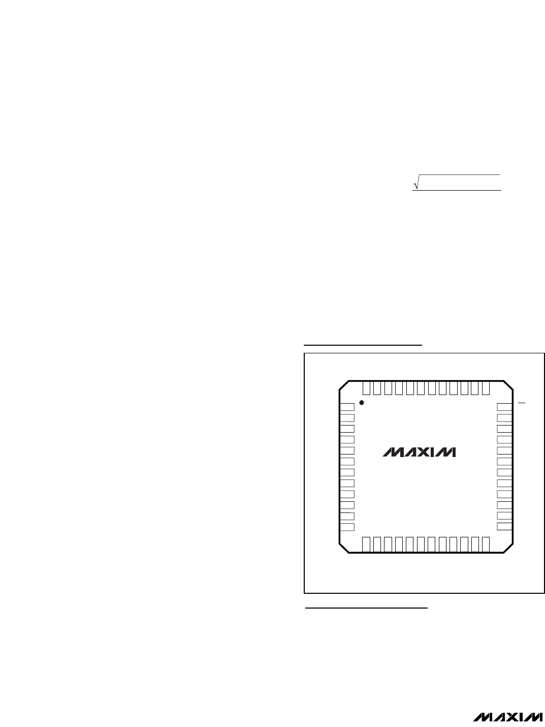
CS
SCLK
V
DD
DD9
DD6
DD5
DD4
DD2
DD3
DD8
DD7
DIN
IA+
IA-
GND
CLK
GND
V
DD
QA-
GND
QA+
V
DD
V
DD
REFP
1
2
3
4
5
6
7
8
9
10
11
12
36
35
34
33
32
31
30
29
28
27
26
25
OGND
OV
DD
DA4
DA6
DD1
DD0
DA7
DA3
DA2
DA1
DA0
COM
REFIN
ID+
ID-
V
DD
GND
QD-
QD+
V
DD
GND
N.C.
REFN
QFN
MAX5864
DA5
TOP VIEW
48
47
46
45
44
43
42
41
40
39
38
37
13
14
15
16
17
18
19
20
21
22
23
24
Pin Configuration