
Datasheet


MAX5823/MAX5824/MAX5825
Ultra-Small, Octal Channel, 8-/10-/12-Bit Buffered
Output DACs with Internal Reference and I
2
C Interface
19Maxim Integrated
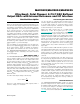
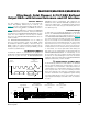
Figure 5. Multiple Register Write Sequence (Standard I
2
C Protocol)
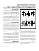
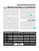
Figure 6. Standard I
2
C Register Read Sequence
I
2
C Write Operations
A master device communicates with the MAX5823/
MAX5824/MAX5825 by transmitting the proper slave
address followed by command and data words. Each
transmit sequence is framed by a START or Repeated
START condition and a STOP condition as described
above. Each word is 8 bits long and is always followed
by an acknowledge clock (ACK) pulse as shown in the
Figure 4 and Figure 5. The first byte contains the address
of the MAX5823/MAX5824/MAX5825 with R/W = 0 to
indicate a write. The second byte contains the register
(or command) to be written and the third and fourth bytes
contain the data to be written. By repeating the register
address plus data pairs (Byte #2 through Byte #4 in
Figure 4 and Figure 5), the user can perform multiple
register writes using a single I
2
C command sequence.
There is no limit as to how many registers the user can
write with a single command. The MAX5823/MAX5824/
MAX5825 support this capability for all user-accessible
write mode commands.
Combined Format I
2
C Readback Operations
Each readback sequence is framed by a START or
Repeated START condition and a STOP condition. Each
word is 8 bits long and is followed by an acknowledge
clock pulse as shown in Figure 6. The first byte contains
the address of the MAX5823/MAX5824/MAX5825 with
R/W = 0 to indicate a write. The second byte contains
the register that is to be read back. There is a Repeated
START condition, followed by the device address with
R/W = 1 to indicate a read and an acknowledge clock.
The master has control of the SCL line but the MAX5823/
MAX5824/MAX5825 take over the SDA line. The final two
bytes in the frame contain the register data readback
followed by a STOP condition. If additional bytes beyond
those required to readback the requested data are pro-
vided, the MAX5823/MAX5824/MAX5825 will continue to
readback ones.
Readback of the WDOG command (B[23:20] = 0001)
is directly supported, confirming the current watchdog
timeout selection, mask status, and safety level.
SCL
AW
20 19 18 17
A
16
15 14 13 12 11 10 9A8
START
SDA
WRITE ADDRESS
BYTE #1: I
2
C SLAVE ADDRESS
WRITE COMMAND1
BYTE #2: COMMAND1 BYTE
(B[23:16])
WRITE DATA1
BYTE #3: DATA1 HIGH BYTE
(B[15:8])
21
0 0 1 A3 A2 A1 A0
2223
STOP
7 6 5 4 3 2 1A0
WRITE DATA1
BYTE #4: DATA1 LOW BYTE
(B[7:0])
20 19 18 17 A16 15 14 13 12 11 10 9A8212223 7 6 5 4 3 2 1A0
ADDITIONAL COMMAND AND
DATA PAIRS (3 BYTE BLOCKS)
COMMAND1
EXECUTED
COMMANDn
EXECUTED
BYTE #5: COMMANDn BYTE
(B[23:16])
BYTE #6: DATAn HIGH BYTE
(B[15:8])
BYTE #7: DATAn LOW BYTE
(B[7:0])
ACK. GENERATED BY MAX5823/MAX5824/MAX5825
A
READ DATA
BYTE #4: DATA1 HIGH
BYTE (B[15:8])
READ DATA
BYTE #5: DATA1 LOW
BYTE (B[15:8])
REPEATED
START
READ ADDRESS
BYTE #3: I
2
C SLAVE
ADDRESS
WRITE ADDRESS
BYTE #1: I
2
C SLAVE
ADDRESS
WRITE COMMAND1
BYTE #2: COMMAND1
BYTE
ACK. GENERATED BY MAX5823/MAX5824/MAX5825 ACK. GENERATED BY I
2
C MASTER
AA
START STOP
SCL
SDA
001A3A2A1A0W AA0
0N
0
01A3 A2 A1 A0 RAD DDDDDDD DDDDDDDD~AANNNNN