
Datasheet


MAX5823/MAX5824/MAX5825
Ultra-Small, Octal Channel, 8-/10-/12-Bit Buffered
Output DACs with Internal Reference and I
2
C Interface
16Maxim Integrated
External Reference
The external reference input has a typical input impedance
of 100kI and accepts an input voltage from +1.24V to V
DD
.
Apply an external voltage between REF and GND to use
an external reference. The MAX5823/MAX5824/MAX5825
power up and reset to external reference mode. Visit
www.maximintegrated.com/products/references for a
list of available external voltage-reference devices.
M/Z Input
The MAX5823/MAX5824/MAX5825 feature a pin select-
able DAC reset state using the M/Z input. Upon a power-
on reset, all CODE and DAC data registers are reset to
zero scale (M/Z = GND) or midscale (M/Z = V
DD
). M/Z is
referenced to V
DD
(not V
DDIO
). In addition, M/Z must be
valid at the time the device is powered up—connect M/Z
directly to V
DD
or GND.
Load DAC (LDAC) Input
The MAX5823/MAX5824/MAX5825 feature an active-low
asynchronous LDAC logic input that allows DAC outputs
to update simultaneously. Connect LDAC to V
DDIO
or
keep LDAC high during normal operation when the
device is controlled only through the serial interface.
Drive LDAC low to update the DAC outputs with data
from the CODE registers. Holding LDAC low causes the
DAC registers to become transparent and CODE data is
passed through to the DAC registers immediately updat-
ing the DAC outputs. A software CONFIG command can
be used to configure the LDAC operation of each DAC
independently.
Clear (CLR) Input
The MAX5823/MAX5824/MAX5825 feature an asynchro-
nous active-low CLR logic input that simultaneously
sets all selected DAC outputs to their programmable
DEFAULT states. Driving CLR low clears the contents of
both the CODE and DAC registers and also ignores any
on-going I
2
C command which modifies registers associ-
ated with a DAC configured to accept clear operations.
To allow a new I
2
C command, drive CLR high, satisfy-
ing the t
CLRSTA
timing requirement. A software CONFIG
command can be used to configure the clear operation of
each DAC independently.
Watchdog Feature
The MAX5823/MAX5824/MAX5825 feature an interface
watchdog timer with programmable timeout duration. This
monitors the I/O interface for activity and integrity. If the
watchdog is enabled, the host processor must write a valid
command to the device within the timeout period to prevent
a timeout. If the watchdog is allowed to timeout, selected
DAC outputs are returned to the programmable DEFAULT
state, protecting the system against control faults.
By default, all watchdog features are disabled; users
wishing to activate any watchdog feature must configure
the device accordingly. Individual DAC channels can
be configured using the CONFIG command to accept
the watchdog alarm and to gate, clear, or hold their out-
puts in response to an alarm. A watchdog refresh event
and watchdog behavior upon timeout is defined by a
programmable safety level using the WDOG_CONFIG
command.
IRQ Output
The MAX5823/MAX5824/MAX5825 feature an active-low
open-drain interrupt output indicating to the host when a
watchdog timeout has occurred.
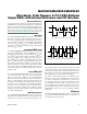
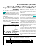
Figure 2. I
2
C START, Repeated START, and STOP Conditions
SCL
SDA
SS
rP
VALID START, REPEATED START, AND STOP PULSES
PS PSPPS
INVALID START/STOP PULSE PAIRINGS-ALL WILL BE RECOGNIZED AS STARTS