
Datasheet


3Maxim Integrated
MAX5713/MAX5714/MAX5715
Ultra-Small, Quad-Channel, 8-/10-/12-Bit Buffered
Output DACs with Internal Reference and SPI Interface
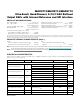
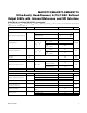
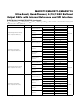
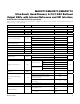
ELECTRICAL CHARACTERISTICS (continued)
(V
DD
= 2.7V to 5.5V, V
DDIO
= 1.8V to 5.5V, V
GND
= 0V, C
L
= 200pF, R
L
= 2kI, T
A
= -40NC to +125NC, unless otherwise noted. Typical
values are at T
A
= +25NC.) (Note 3)
PARAMETER SYMBOL CONDITIONS MIN TYP MAX UNITS
DAC OUTPUT
CHARACTERISTICS
Output Voltage Range (Note 7)
No load 0 V
DD
V2kI load to GND 0
V
DD
-
0.2
2kI load to V
DD
0.2 V
DD
Load Regulation V
OUT
= V
FS
/2
V
DD
= 3V Q10%,
|I
OUT
| P 5mA
300
FV/mA
V
DD
= 5V Q10%,
|I
OUT
| P 10mA
300
DC Output Impedance V
OUT
= V
FS
/2
V
DD
= 3V Q10%,
|I
OUT
| P 5mA
0.3
I
V
DD
= 5V Q10%,
|I
OUT
| P 10mA
0.3
Maximum Capacitive Load
Handling
C
L
500 pF
Resistive Load Handling R
L
2 kI
Short-Circuit Output Current V
DD
= 5.5V
Sourcing (output
shorted to GND)
30
mA
Sinking (output
shorted to V
DD
)
50
DC Power-Supply Rejection V
DD
= 3V Q10% or 5V Q10% 100 FV/V
DYNAMIC PERFORMANCE
Voltage-Output Slew Rate SR Positive and negative 1.0 V/Fs
Voltage-Output Settling Time
¼ scale to ¾ scale, to P 1 LSB, MAX5713 2.2
Fs¼ scale to ¾ scale, to P 1 LSB, MAX5714 2.6
¼ scale to ¾ scale, to P 1 LSB, MAX5715 4.5
DAC Glitch Impulse Major code transition 7 nV*s
Channel-to-Channel
Feedthrough (Note 8)
External reference 3.5
nV*s
Internal reference 3.3
Digital Feedthrough
Code = 0, all digital inputs from 0V to
V
DDIO
0.2 nV*s
Power-Up Time
Startup calibration time (Note 9) 200 Fs
From power-down 50 Fs