
Datasheet


21Maxim Integrated
MAX5713/MAX5714/MAX5715
Ultra-Small, Quad-Channel, 8-/10-/12-Bit Buffered
Output DACs with Internal Reference and SPI Interface
POWER Command
The MAX5713/MAX5714/MAX5715 feature a software-
controlled power-mode (POWER) command (B[23:20] =
0100). The POWER command updates the power-mode
settings of the selected DACs while the power settings of
the rest of the DACs remain unchanged. The new power
setting is determined by bits B[17:16] while the affected
DAC(s) are selected by bits B[11:8]. If all DACs are pow-
ered down, the device enters a STANDBY mode.
In power-down, the DAC output is disconnected from
the buffer and is grounded with either one of the two
selectable internal resistors or set to high impedance.
See Table 5 for the selectable internal resistor values in
power-down mode. In power-down mode, the DAC regis-
ter retains its value so that the output is restored when the
device powers up. The serial interface remains active in
power-down mode.
In STANDBY mode, the internal reference can be pow-
ered down or it can be set to remain powered-on for
external use. Also, in STANDBY mode, devices using the
external reference do not load the REF pin. See Table 4.
SW_RESET and SW_CLEAR Command
The SW_RESET (B[23:16] = 01010001) and SW_CLEAR
(B[23:16] = 01010000) commands provide a means of
issuing a software reset or software clear operation. Use
SW_CLEAR to issue a software clear operation to return
all CODE and DAC registers to the zero-scale value. Use
SW_RESET to reset all CODE, DAC, and configuration
registers to their default values.
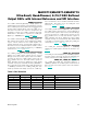
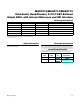
Table 4. POWER (100) Command Format
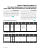
Table 5. Selectable DAC Output Impedance in Power-Down Mode
B23 B22 B21 B20 B19 B18 B17 B16 B15 B14 B13 B12 B11 B10 B9 B8 B7 B6 B5 B4 B3 B2 B1 B0
0 1 0 0 0 0 PD1 PD0 X X X X D C B A X X X X X X X X
POWER Command
Power
Mode:
00 =
Normal
01 = 1kI
10 =
100kI
11 = Hi-Z
Don’t Care
Multiple DAC
Selection:
1 = DAC Selected
0 = DAC Not
Selected
Don’t Care
Default Values (all DACs) ➝ 0 0 X X X X 1 1 1 1 X X X X X X X X
PD1 (B17) PD0 (B16) OPERATING MODE
0 0 Normal operation
0 1
Power-down with internal 1kI pulldown resistor to GND.
1 0
Power-down with internal 100kI pulldown resistor to GND.
1 1 Power-down with high-impedance output.