
Datasheet


19Maxim Integrated
MAX5713/MAX5714/MAX5715
Ultra-Small, Quad-Channel, 8-/10-/12-Bit Buffered
Output DACs with Internal Reference and SPI Interface
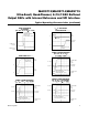
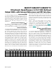
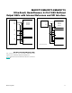
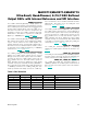
Table 2. SPI Commands Summary (continued)
COMMAND B23 B22 B21 B20 B19 B18 B17 B16 B15 B14 B13 B12 B11 B10 B9 B8 B7 B6 B5 B4 B3 B2 B1 B0 DESCRIPTION
CONFIG 0 1 1 0
All DACs
0 0
LD_EN
X X X X
DAC D
DAC C
DAC B
DAC A
X X X X X X X X
Sets the DAC Latch Mode
of the selected DACs.
Only DACS with a 1 in the
selection bit are updated
by the command.
LD_EN = 0: DAC latch is
operational (LOAD and
LDAC controlled)
LD_EN = 1: DAC latch is
transparent
REF 0 1 1 1 0
REF
Power
0 =
DAC
1 =
ON
REF
Mode
00 = EXT
01 = 2.5V
10 = 2.0V
11 = 4.1V
X X X X X X X X X X X X X X X X
Sets the reference
operating mode.
REF Power (B18):
0 = Internal reference is
only powered if at least one
DAC is powered
1 = Internal reference is
always powered
ALL DAC COMMANDS
CODE_ALL 1 0 0 0 0 0 0 0
CODE REGISTER
DATA [11:4]
CODE REGISTER
DATA [3:0]
X X X X
Writes data to all CODE
registers
LOAD_ALL 1 0 0 0 0 0 0 1 X X X X X X X X X X X X X X X X
Updates all DAC latches
with current CODE register
data
CODE_
ALL_
LOAD_ALL
1 0 0 0 0 0 1 X
CODE REGISTER
DATA [11:4]
CODE REGISTER
DATA [3:0]
X X X X
Simultaneously writes data
to all CODE registers while
updating all DAC registers
NO OPERATION COMMANDS
No
Operation
1 0 0 1 X X X X X X X X X X X X X X X X X X X X
These commands will have
no effect on the device
1 0 1 X X X X X X X X X X X X X X X X X X X X X
1 1 X X X X X X X X X X X X X X X X X X X X X X
Reserved Commands: Any commands not specifically listed above are reserved for Maxim internal use only.