
Datasheet


14Maxim Integrated
MAX5713/MAX5714/MAX5715
Ultra-Small, Quad-Channel, 8-/10-/12-Bit Buffered
Output DACs with Internal Reference and SPI Interface
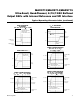
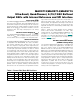
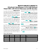
Pin/Bump Description
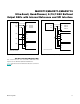
Pin/Bump Configurations
PIN BUMP
NAME FUNCTION
TSSOP WLP
1 B1 REF Reference Voltage Input/Output
2 A1 OUTA Buffered Channel A DAC Output
3 A2 OUTB Buffered Channel B DAC Output
4 B2 GND Ground
5 A3 OUTC Buffered Channel C DAC Output
6 A4 OUTD Buffered Channel D DAC Output
7 B4 V
DD
Supply Voltage Input. Bypass V
DD
with a 0.1FF capacitor to GND.
8 —
RDY
SPI RDY Output. In daisy-chained applications connect RDY to the CSB of the next
device in the chain.
9 C4 DIN SPI Interface Data Input
10 C3 SCLK SPI Interface Clock Input
11 C2 CSB SPI Chip-Select Input
12 C1
CLR
Active-Low Clear Input
13 B3 V
DDIO
Digital Interface Power-Supply Input
14 —
LDAC
Load DAC. Active-low hardware load DAC input.
14
13
12
11
10
9
8
1
2
3
4
5
6
7
LDAC
V
DDIO
CLR
CSBGND
OUTB
OUTA
REF
TOP VIEW
MAX5713
MAX5714
MAX5715
SCLK
DIN
RDYV
DD
OUTD
OUTC
TSSOP
+
WLP
TOP VIEW
DINCLR
V
DD
REF
OUTDOUTA
MAX5715
+
1 2 34
A
CSBSCLK
GND V
DDIO
OUTB OUTC
B
C