
Datasheet


MAX5532–MAX5535
Dual, Ultra-Low-Power,
12-Bit, Voltage-Output DACs
16 ______________________________________________________________________________________
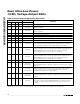
Table 2. Serial-Interface Programming Commands
CONTROL BITS INPUT DATA
C3
C2 C1 C0
D11–D0
FUNCTION
0 0 0 0 XXXXXXXXXXXX No operation; command is ignored.
0 0 0 1 12-bit data
Load input register A from shift register; DAC registers unchanged; DAC
outputs unchanged.
0 0 1 0 12–bit data
Load input register B from shift register; DAC registers unchanged; DAC
outputs unchanged.
0 0 1 1 — Command reserved. Do not use.
0 1 0 0 — Command reserved. Do not use.
0 1 0 1 — Command reserved. Do not use.
0 1 1 0 — Command reserved. Do not use.
0 1 1 1 — Command reserved. Do not use.
1 0 0 0 12-bit data
Load DAC registers A and B from respective input registers; DAC outputs A
and B updated; MAX5533/MAX5535 enter normal operation if in standby or
shutdown; MAX5532/MAX5534 enter normal operation if in shutdown.
1 0 0 1 12-bit data
Load input register A and DAC register A from shift register; DAC output A
updated; Load DAC register B from input register B; DAC output B updated;
MAX5533/MAX5535 enter normal operation if in standby or shutdown;
MAX5532/MAX5534 enter normal operation if in shutdown.
1 0 1 0 12-bit data
Load input register B and DAC register B from shift register; DAC output B
updated; Load DAC register A from input register A; DAC output A updated;
MAX5533/MAX5535 enter normal operation if in standby or shutdown;
MAX5532/MAX5534 enter normal operation if in shutdown.
1 0 1 1 — Command reserved. Do not use.
1100
D11, D10,
XXXXXXXXXX
MAX5533/MAX5535 enter standby*, MAX5532/MAX5534 enter shutdown. For
the MAX5533/MAX5535, D11 and D10 configure the internal reference voltage
(Table 3).
1101
D11, D10,
XXXXXXXXXX
MAX5532–MAX5535 enter normal operation; DAC outputs reflect existing
contents of DAC registers. For the MAX5533/MAX5535, D11 and D10
configure the internal reference voltage (Table 3).
1110
D11, D10,
XXXXXXXXXX
MAX5532–MAX5535 enter shutdown; DAC outputs set to high impedance. For
the MAX5533/MAX5535, D11 and D10 configure the internal reference voltage
(Table 3).
1 1 1 1 12-bit data
Load input registers A and B and DAC registers A and B from shift register;
DAC outputs A and B updated; MAX5533/MAX5535 enter normal operation if
in standby or shutdown; MAX5532/MAX5534 enter normal operation if in
shutdown.
X = Don’t care.
*Standby mode can be entered from normal operation only. It is not possible to enter standby mode from shutdown.