
Datasheet


Dual, 256-Tap, Volatile, Low-Voltage,
Linear Taper Digital Potentiometer
MAX5392
______________________________________________________________________________________ 11
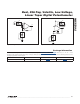
Figure 3. START and STOP Conditions
Figure 4. Slave Address
Figure 5. Bit Transfer
Each transmission consists of a START (S) condition sent
by a master, followed by a 7-bit slave address plus a
NOP/W bit. See Figures 3, 4, and 7.
START and STOP Conditions
SCL and SDA remain high when the interface is inactive.
A master controller signals the beginning of a transmis-
sion with a START condition by transitioning SDA from
high to low while SCL is high. The master controller
issues a STOP condition by transitioning the SDA from
low to high while SCL is high, after finishing communi-
cating with the slave. The bus is then free for another
transmission. See Figure 2.
Bit Transfer
One data bit is transferred during each clock pulse. The
data on the SDA line must remain stable while SCL is
high. See Figure 5.
Acknowledge
The acknowledge bit is a clocked 9th bit that the recipi-
ent uses to handshake receipt of each byte of data. See
Figure 6. Each byte transferred requires a total of 9 bits.
The master controller generates the 9th clock pulse, and
the recipient pulls down SDA during the acknowledge
clock pulse, so the SDA line remains stable low during
the high period of the clock pulse.
P
STOP
CONDITION
S
START CONDITION
SDA
SCL
LSBMSB
START
SDA
SCL
0 1 0 1 A2 A1 A0 ACKNOP/W
SDA
SCL
DATA STABLE,
DATA VALID
CHANGE OF
DATA ALLOWED