
Datasheet


Variable Gain Current to Voltage Converter
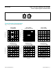
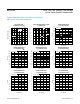
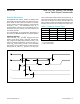
Figure 7 shows a variable gain current to voltage con-
verter using a potentiometer as a variable resistor.
LCD Bias Control
Figure 8 shows a positive LCD bias control circuit using a
potentiometer as a voltage-divider.
Figure 9 shows a positive LCD bias control circuit using a
potentiometer as a variable resistor
Programmable Filter
Figure 10 shows a programmable filter using a dual
potentiometer.
Offset Voltage Adjustment Circuit
Figure 11 shows an offset voltage adjustment circuit using
a dual potentiometer
Figure 7. Variable Gain I-to-V Converter Figure 9. Positive LCD Bias Control Using a Variable Resistor
Figure 10. Programmable FilterFigure 8. Positive LCD Bias Control Using a Voltage-Divide
L
R1
R2
R3
V
OUT
I
S
H
W
V
OUT
= -I
S
x ((R3 x (1 + R2/R1)) + R2)
L
V
OUT
H
W
+5V
L
V
OUT
H
W
+5V
V
OUT
V
IN
LA
HA
WB
LB
HB
R2
R1
R3
WA
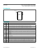
MAX5389 Dual, 256-Tap, Volatile, Low-Voltage
Linear Taper Digital Potentiometer
www.maximintegrated.com
Maxim Integrated
│
11