
Datasheet


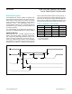


Applications Information
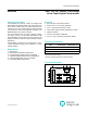
Variable Gain Amplier
Figure 3 shows a potentiometer adjusting the gain of a
noninverting amplifier. Figure 4 shows a potentiometer
adjusting the gain of an inverting amplifier.
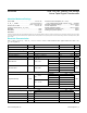
Adjustable Dual Linear Regulator
Figure 5 shows an adjustable dual linear regulator using a
dual potentiometer as two variable resistors.
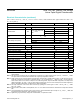
Adjustable Voltage Reference
Figure 6 shows an adjustable voltage reference circuit
using a potentiometer as a voltage-divider.
Figure 3. Variable Gain Noninverting Amplifier
V
IN
V
OUT
H
L
W
V
IN
V
OUT
H
L
W
V
OUT1
V
OUT2
OUT1
OUT2
SET1
SET2
IN
V+
L
L
H
H
W
W
MAX8866
OUT
IN
+5V
V
REF
GND
L
H
W
MAX6160
Figure 5. Adjustable Dual Linear Regulator
Figure 6. Adjustable Voltage ReferenceFigure 4. Variable Gain Inverting Amplifier
MAX5389 Dual, 256-Tap, Volatile, Low-Voltage
Linear Taper Digital Potentiometer
www.maximintegrated.com
Maxim Integrated
│
10