
Datasheet


V
DD
to GND ............................................................-0.3V to +6V
H_, W_, L_ to GND ..................................... -0.3V to the lower of
(V
DD
+ 0.3V) and +6V
All Other Pins to GND..............................................-0.3V to +6V
Continuous Current into H_, W_, and L_
MAX5387L ......................................................................±5mA
MAX5387M .....................................................................±2mA
MAX5387N .....................................................................±1mA
Continuous Power Dissipation (T
A
= +70ºC)
14-Pin TSSOP (derate 10mW/ºC above +70ºC) ......796.8mW
Operating Temperature Range ..........................-40ºC to +125ºC
Junction Temperature ......................................................+150ºC
Storage Temperature Range .............................-65ºC to +150ºC
Lead Temperature (soldering, 10s) ................................. +300ºC
Soldering Temperature (reflow) .......................................+260ºC
(V
DD
= +2.6V to +5.5V, V
H_
= V
DD
, V
L_
= GND, T
A
= -40ºC to +125ºC, unless otherwise noted. Typical values are at V
DD
= +5V,
T
A
= +25ºC.) (Note 1)
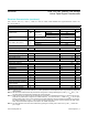
PARAMETER SYMBOL CONDITIONS MIN TYP MAX UNITS
Resolution N 256 Tap
DC PERFORMANCE (Voltage-Divider Mode)
Integral Nonlinearity INL (Note 2) -0.5 +0.5 LSB
Differential Nonlinearity DNL (Note 2) -0.5 +0.5 LSB
Dual Code Matching Register A = register B -0.5 +0.5 LSB
Ratiometric Resistor Tempco (ΔV
W
/Δ
W
)/ΔT; no load +5 LSB
Full-Scale Error Code = FFH
MAX5387L -3 -2.5
LSBMAX5387M -1 -0.5
MAX5387N -0.5 -0.25
Zero-Scale Error Code = 00H
MAX5387L +2.5 +3
LSBMAX5387M +0.5 +1.0
MAX5387N +0.25 +0.5
DC PERFORMANCE (Variable-Resistor Mode)
Integral Nonlinearity R-INL
V
DD
> +2.6V
MAX5387L ±1.0 ±2.5
LSB
MAX5387M ±0.5 ±1.0
MAX5387N ±0.25 ±0.8
V
DD
> +4.75V
MAX5387L ±0.4 ±1.5
MAX5387M ±0.3 ±0.75
MAX5387N ±0.25 ±0.5
Differential Nonlinearity R-DNL V
DD
> 2.6V (Note 3) -0.5 +0.5 LSB
DC PERFORMANCE (Resistor Characteristics)
Wiper Resistance (Note 4) R
WL
V
DD
> 2.6V 250 600
Ω
V
DD
> 4.75V 150 200
Terminal Capacitance C
H_
, C
L_
Measured to GND 10 pF
Wiper Capacitance C
W_
Measured to GND 50 pF
End-to-End Resistor Tempco TC
R
No load 35 ppm/ºC
End-to-End Resistor Tolerance ΔR
HL
Wiper not connected -25 +25 %
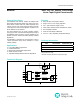
MAX5387 Dual, 256-Tap, Volatile, Low-Voltage
Linear Taper Digital Potentiometer
www.maximintegrated.com
Maxim Integrated
│
2
Absolute Maximum Ratings
Stresses beyond those listed under “Absolute Maximum Ratings” may cause permanent damage to the device. These are stress ratings only, and functional operation of the device at these
or any other conditions beyond those indicated in the operational sections of the specifications is not implied. Exposure to absolute maximum rating conditions for extended periods may affect
device reliability.
Electrical Characteristics