
Datasheet


Variable Gain Current to Voltage Converter
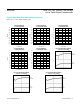
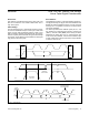
Figure 12 shows a variable gain current to voltage con-
verter using a potentiometer as a variable resistor.
LCD Bias Control
Figure 13 shows a positive LCD bias control circuit using
a potentiometer as a voltage-divider.
Figure 14 shows a positive LCD bias control circuit usinga
potentiometer as a variable resistor.
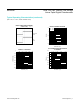
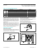
Programmable Filter
Figure 15 shows a programmable filter using a dual
potentiometer.
Offset-Voltage Adjustment Circuit
Figure 16 shows an offset-voltage adjustment circuit
using a dual potentiometer.
Figure 11. Adjustable Voltage Reference Figure 13. Positive LCD Bias Control Using a Voltage-Divider
Figure 12. Variable Gain I-to-V Converter Figure 14. Positive LCD Bias Control Using a Variable Resistor
OUT
IN
3.0V
V
REF
GND
L
H
W
MAX6037
L
V
OUT
H
W
+5V
L
R1
R2
R3
V
OUT
I
S
H
W
V
OUT
= -I
S
x ((R3 x (1 + R2/R1)) + R2)
L
V
OUT
H
W
+5V
MAX5387 Dual, 256-Tap, Volatile, Low-Voltage
Linear Taper Digital Potentiometer
www.maximintegrated.com
Maxim Integrated
│
13