
Datasheet


REG B: The data byte writes to register B and the wiper of
potentiometer B moves to the appropriate position. D[7:0]
indicates the position of the wiper. D[7:0] = 00h moves the
wiper to the position closest to LB. D[7:0] = FFh moves
the wiper to the position closest to HB. D[7:0] is 80h fol-
lowing power-on.
REGS A and B: The data byte writes to registers A and
B and the wipers of potentiometers A and B move to the
appropriate position. D[7:0] indicates the position of the
wiper. D[7:0] = 00h moves the wipers to the position clos-
est to L_. D[7:0] = FFh moves the wipers to the position
closest to H_. D[7:0] is 80h following power-on.
Applications Information
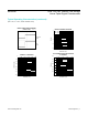
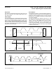
Variable Gain Amplier
Figure 8 shows a potentiometer adjusting the gain of a
noninverting amplifier. Figure 9 shows a potentiometer
adjusting the gain of an inverting amplifier.
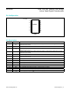
Adjustable Dual Regulator
Figure 10 shows an adjustable dual linear regulator using
a dual potentiometer as two variable resistors.
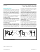
Adjustable Voltage Reference
Figure 11 shows an adjustable voltage reference circuit
using a potentiometer as a voltage-divider.
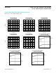
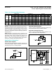
Table 2. I
2
C Command Byte Summary
Figure 8. Variable Gain Noninverting Amplifier
Figure 9. Variable Gain Inverting Amplifier
Figure 10. Adjustable Dual Linear Regulator
ADDRESS BYTE COMMAND BYTE DATA BYTE
SCL
CYCLE NO.
START (S)
1 2 3 4 5 6 7 8 9 10 11 12 13 14 15 16 17 18 19 20 21 22 23 24 25 26 27
STOP (P)
A6 A5 A4 A3 A2 A1 A0 W
ACK
(A)
R7 R6 R5 R4 R3 R2 R1 R0
ACK
(A)
D7 D6 D5 D4 D3 D2 D1 D0
ACK
(A)
REG A 0 1 0 1 A2 A1 A0 0 0 0 0 1 0 0 0 1 D7 D6 D5 D4 D3 D2 D1 D0
REG B 0 1 0 1 A2 A1 A0 0 0 0 0 1 0 0 1 0 D7 D6 D5 D4 D3 D2 D1 D0
REGS
A AND B
0 1 0 1 A2 A1 A0 0 0 0 0 1 0 0 1 1 D7 D6 D5 D4 D3 D2 D1 D0
V
IN
V
OUT
H
L
W
V
IN
V
OUT
H
L
W
V
OUT1
V
OUT2
OUT1
OUT2
SET1
SET2
IN
V+
L
L
H
H
W
W
MAX8866
MAX5387 Dual, 256-Tap, Volatile, Low-Voltage
Linear Taper Digital Potentiometer
www.maximintegrated.com
Maxim Integrated
│
12