
Datasheet
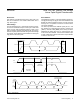


Message Format for Writing
Write to the devices by transmitting the device’s slave
address with NOP/W (eighth bit) set to zero, followed by
at least 2 bytes of information. The first byte of information
is the command byte. The second byte is the data byte.
The data byte goes into the internal register of the device
as selected by the command byte (Figure 7 and Table 2).
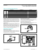
Command Byte
Use the command byte to select the destination of the
wiper data. See Table 2.
Command Descriptions
REG A: The data byte writes to register A and the wiper of
potentiometer A moves to the appropriate position. D[7:0]
indicates the position of the wiper. D[7:0] = 00h moves the
wiper to the position closest to LA. D[7:0] = FFh moves
the wiper to the position closest to HA. D[7:0] is 80h fol-
lowing power-on.
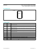
Table 1. Slave Addresses
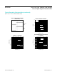
Figure 6. Slave Address
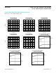
Figure 7. Command and Single Data Byte Received
ADDRESS INPUTS
SLAVE ADDRESS
A2 A1 A0
GND GND GND 0101000
GND GND V
DD
0101001
GND V
DD
GND 0101010
GND V
DD
V
DD
0101011
V
DD
GND GND 0101100
V
DD
GND V
DD
0101101
V
DD
V
DD
GND 0101110
V
DD
V
DD
V
DD
0101111
LSBMSB
START
SDA
SCL
0 1 0 1 A2 A1 A0 ACKNOP/W
S 0 A A A P
ACKNOWLEDGE
NOP/W
HOW CONTROL BYTE AND DATA
BYTE MAP INTO DEVICE REGISTERS
ACKNOWLEDGE
R7 R6 R5 R4 R3 R2 R1 R0 D7 D6 D5 D4 D3 D2 D1 D0
SLAVE ADDRESS COMMAND BYTE 1 DATA BYTE
MAX5387 Dual, 256-Tap, Volatile, Low-Voltage
Linear Taper Digital Potentiometer
www.maximintegrated.com
Maxim Integrated
│
11