
Datasheet


MAX532
Dual, Serial-Input,
Voltage-Output, 12-Bit MDAC
2 _______________________________________________________________________________________
Pin Voltages
V
DD
to DGND, AGNDA, AGNDB........................-0.3V to +17V
V
SS
to DGND, AGNDA, AGNDB (Note 1) ..........+0.3V to -17V
VREFA, VREFB.............................(V
SS
- 0.3V) to (V
DD
+ 0.3V)
AGNDA, AGNDB.....................(DGND - 0.3V) to (V
DD
+ 0.3V)
VOUTA, VOUTB...........................(V
SS
- 0.3V) to (V
DD
+ 0.3V)
RFBA, RFBB.................................(V
SS
- 0.3V) to (V
DD
+ 0.3V)
SCLK, DIN, DOUT, LDAC, CS ..(DGND - 0.3V) to (V
DD
+ 0.3V)
DOUT Sink Current .............................................................20mA
Continuous Power Dissipation (T
A
= +70°C)
Plastic DIP (derate 10.53mW/°C above +70°C) ..........842mW
Wide SO (derate 9.52mW/°C above +70°C)................762mW
CERDIP (derate 10.00mW/°C above +70°C)...............800mW
Operating Temperature Ranges:
MAX532_C__ ......................................................0°C to +70°C
MAX532_E__....................................................-40°C to +85°C
MAX532_MJE ................................................-55°C to +125°C
Junction Temperatures:
MAX532_C__, E__........................................................+150°C
MAX532_MJE...............................................................+175°C
Storage Temperature Range........................... -65°C to +160°C
Lead Temperature (soldering, 10sec)........................... +300°C
ELECTRICAL CHARACTERISTICS
(V
DD
= 11.4V to 16.5V, V
SS
= -11.4V to -16.5V, AGNDA = AGNDB = DGND = 0V, VREFA and VREFB = +10V, R
L
= 2kΩ,
C
L
= 100pF, VOUT_ connected to RFB_, T
A
= T
MIN
to T
MAX
, unless otherwise noted.)
Stresses beyond those listed under “Absolute Maximum Ratings” may cause permanent damage to the device. These are stress ratings only, and functional
operation of the device at these or any other conditions beyond those indicated in the operational sections of the specifications is not implied. Exposure to
absolute maximum rating conditions for extended periods may affect device reliability.
ABSOLUTE MAXIMUM RATINGS
PARAMETER CONDITIONS MIN TYP MAX UNITSSYMBOL
Resolution
INL
12 Bits
Relative Accuracy
±1
LSB
Differential Nonlinearity Guaranteed monotonic ±1 LSB
±1/2MAX532A
MAX532B
±2
T
A
= +25°C, MAX532_
±3Zero-Code Offset Error
DAC latch loaded
with all 0s
±4
mV
T
A
= T
MIN
to T
MAX
, MAX532B
±5 µV/°CDAC latch loaded with all 0s
±2MAX532A
T
A
= +25°C, DAC latch
loaded with all 1s
±5MAX532B
±0.5 ±3.0 %
81013kΩ
±2
ppm/°C
of FSR
Gain Error
T
A
= T
MIN
to T
MAX
, DAC
latch loaded with all 1s
±7
LSB
MAX532B
±4MAX532A
T
A
= T
MIN
to T
MAX
, MAX532A
Zero-Code Offset
Temperature Coefficient
Gain-Error Temperature
Coefficient
VREFA, VREFB Input
Resistance
VREFA, VREFB Input
Resistance Matching
STATIC PERFORMANCE (Note 1)
REFERENCE INPUTS (VREFA, VREFB)
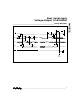
Note 1: If V
SS
is open-circuited with V
DD
and either AGND applied, the V
SS
pin will float positive, exceeding the Absolute Maximum Ratings.
A Schottky diode connected between V
SS
and GND ensures the maximum ratings will not be exceeded.