
Datasheet


28Maxim Integrated
MAX5318
18-Bit, High-Accuracy Voltage Output DAC with
Digital Gain, Offset Control, and SPI Interface
LDAC and BUSY Interaction
The BUSY line is open drain and is normally pulled up
by an external resistor. It is software-configurable bidi-
rectional and can be pulled down externally. If any of the
DIN, GAIN, and OFFSET registers is changed, the device
must calculate the value to be presented to the DAC reg-
ister. To indicate to the host processor that the device is
busy, the device pulls the BUSY output low. Once com-
putation is complete, the device releases BUSY and the
host processor can load the DAC by toggling the LDAC
input. If LDAC is set low while BUSY is low, the LDAC
event is latched and implemented when the computation
is complete and BUSY rises.
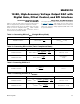
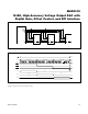
There are four ways in which the LDAC and BUSY out-
puts can be used. This is shown graphically in Figure 6.
1) The host sends a new command. The device sets BUSY
low. The host monitors BUSY to determine when it goes
high. The device then pulses LDAC low to update the
DAC.
2) The host sends a new command. The device sets
BUSY low. The host toggles LDAC low then high
before BUSY goes high. The device latches the LDAC
event but does not implement it until processing is
complete. Then, BUSY goes high and the device
updates the DAC.
3) LDAC is held low. The host sends a new command
and the device sets BUSY low. The device updates
the DAC when the processing is complete and BUSY
goes high.
4)
BUSY is pulled down externally to delay DAC update.
The BUSY pin is bidirectional. To use BUSY as an
input, set the NO_BUSY bit to 1 using the 0x4 or 0xC
command. When configured as an input, pulling BUSY
low at least 50ns before the device releases the line
delays DAC update. DAC update occurs only after
BUSY is released and goes high. If used as an input,
drive BUSY with an open-drain output with a pullup
to V
DDIO
. The processing required for calculating the
final DAC code is controlled by an internally generated
clock. The clock frequency is not related to any exter-
nal signals and the frequency is not precisely defined.
Therefore, if the DAC must be updated at a precise
time with the least amount of jitter, use option 1.
Figure 6. BUSY and LDAC Timing
DIN
SCLK
BUSY
BUSY
LDAC
LDAC
LDAC
LDAC
V
OUT
V
OUT
V
OUT
V
OUT
OPTION 1
INPUT REGISTER LOADED
OPTION 2
OPTION 3
OPTION 4
(USED AS INPUT)
X1 2X21 22
23
X
t
BUSY
t
S
t
CBF
t
LDH
50ns
t
LDPW
BUSY PULLED LOW EXTERNALLY