
Datasheet
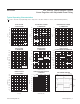
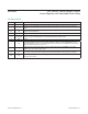

PIN NAME FUNCTION
1, 12–16 N.C. No Connection. Not internally connected.
2 EN
Enable Input. Drive EN high to turn on the regulator. Force EN low to place the device in shutdown
mode.
3, 4 IN
Regulator Input. Supply voltage ranges from 6.5V to 45V. Bypass IN to GND with a low ESR 47µF
capacitor (electrolytic 50VL).
5, 6 OUT Regulator Output. Connect at least a 15µF low-ESR capacitor from OUT to GND.
7 OUTSENSE
Regulator Output Feedback Point. OUTSENSE must be connected to OUT for xed output voltage
versions. Leave OUTSENSE open circuit for adjustable output voltage version.
8 GND Ground
9 SET
Feedback Regulation Set Point. Connect SET to GND for a xed 3.3V output (MAX5086A) or 5.0V
output (MAX5086B). Connect an external resistive divider network from OUTSENSE to SET to GND to
adjust the output voltage from 2.5V to 11V.
10 RESET
Open-Drain Active-Low Reset Output. Connect a 10kΩ pullup resistor from RESET to any supply
voltage up to 11V to create a logic output.
11 CT
Reset Timeout Setting Connection. A 2µA charging current is available at CT. Connect a capacitor from
CT to GND to set the reset timeout period (see the Adjustable Reset Timeout Period (CT) section).
EP EP
Exposed Pad. Connect externally to a large ground plane to aid heat dissipation. Do not use EP as the
only ground connection.
MAX5086 45V, 250mA, Low-Quiescent-Current
Linear Regulator with Adjustable Reset Delay
www.maximintegrated.com
Maxim Integrated
│
6
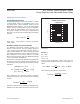
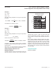
Pin Description