
Datasheet

Example 2:
T
A
= +125°C
V
IN
= +14V
V
OUT
= +5V
Calculate package dissipation at the given temperature
as follows:
D
W
P 2.666W 0.0333 (125 C 70 C) 0.8345W
C
= − °−° =
°
And establish the maximum current:
OUT(MAX)
(0.8345W)
I 92mA
(14V) (5V)
= =
−
Example 3:
T
A
= +50°C
V
IN
= +14V
V
OUT
= +5V
Calculate package dissipation at the given temperature
as follows:
P
D
= 2.666W
And find the maximum output current:
OUT(MAX) OUT(MAX)
(2.666W)
I 296mA I 250mA
(14V) (5V)
= =⇒=
−
In Example 3, the maximum output current is calculated
as 296mA, however, the maximum output current cannot
exceed 250mA.
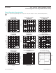
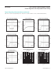
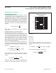
Use Figure 4 to quickly determine maximum allowable
output current for selected ambient temperatures.
Output Capacitor Selection and
Regulator Stability
For stable operation over the full temperature range and
with load currents up to 250mA, use a 15µF (min) output
capacitor with an ESR < 0.25Ω. To reduce noise and
improve load-transient response, stability, and power-
supply rejection, use larger output capacitor values such
as 22µF.
Some ceramic capacitor dielectrics exhibit large capaci-
tance and ESR variation with temperature. For capacitor
dielectrics such as Y5V, use 22µF or more to ensure
stability at temperatures below -10°C. With X7R or X5R
dielectrics, 15µF should be sufficient at all operating tem-
peratures. To improve power supply rejection and tran-
sient response, use a minimum 47µF low ESR capacitor
from IN to GND.
Figure 4. Maximum Output Current vs. Input Voltage
MAXIMUM OUTPUT CURRENT
vs. INPUT VOLTAGE
MAX5086 fig04
V
IN
(V)
I
OUT(MAX)
(A)
45403530252015105
0.05
0.10
0.15
0.20
0.25
0.30
0
0
V
OUT
= +5V
T
A
= +70°C
T
A
= +85°C
T
A
= +125°C
MAX5086 45V, 250mA, Low-Quiescent-Current
Linear Regulator with Adjustable Reset Delay
www.maximintegrated.com
Maxim Integrated
│
10
Chip Information
PROCESS: BiCMOS