
Datasheet


MAX5068
High-Frequency, Current-Mode PWM Controller
with Accurate Programmable Oscillator
4 _______________________________________________________________________________________
Note 1: The MAX5068 is 100% tested at T
A
= +25°C. All limits over temperature are guaranteed by design.
Note 2: The MAX5068A/B are intended for use in universal-input power supplies. The internal clamp circuit is used to prevent the
bootstrap capacitor (C1 in Figure 1) from charging to a voltage beyond the absolute maximum rating of the device when
UVLO/EN is low. The maximum current to V
IN
(hence to clamp) when UVLO is low (device is in shutdown) must be external-
ly limited to 2mA. Clamp currents higher than 2mA may result in clamp voltages higher than 30V, thus exceeding the
absolute maximum rating for V
IN
. For the MAX5068C/D, do not exceed the 24V maximum operating voltage of the device.
Note 3: Reference voltage (V
REF
) is measured with FB connected to COMP (see the Functional Diagram).
Note 4: The SYNC frequency must be at least 25% higher than the programmed oscillator frequency.
Note 5: The internal oscillator clock cycle.
Note 6: The MAX5068A/B driver switching frequency is one-half of the oscillator frequency. The MAX5068C/D/E/F driver switching
frequency is one-quarter of the oscillator frequency.
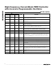
PARAMETER SYMBOL CONDITIONS MIN TYP MAX UNITS
f
SW
= 10
11
/(2 x R
RT
),
MAX5068A/B
25 1250 kHz
NDRV Switching Frequency f
SW
(Note 6)
f
SW
= 10
11
/(4 x R
RT
),
MAX5068C/D/E/F
12.5 625 kHz
RT Voltage V
RT
40kΩ < R
RT
< 500kΩ 2.0 V
f
OSC
≤ 500kHz -2.5 +2.5
T
A
= +25°C
f
OSC
> 500kHz -4 +4
f
OSC
≤ 500kHz -4.5 +4.5
Oscillator Accuracy
T
A
= - 40° C to + 125° C
f
OSC
> 500kHz -6 +6
%
MAX5068A/B 50
Maximum Duty Cycle D
MAX
DT connected to
REG5
MAX5068C/D/E/F 75
%
DEAD-TIME CONTROL (DT)
Dead Time t
DT
R
DT
= 24.9kΩ 60 ns
Dead-Time Disable Voltage V
D T_D IS ABLE
V
REG5
- 0.5V
V
Dead-Time Regulation Voltage V
DT
1.23 V
INTEGRATING FAULT PROTECTION (FLTINT)
FLTINT Source Current I
FLTINT
V
FLTINT
= 0 60 µA
FLTINT Shutdown Threshold V
FLTINT_SD
V
FLTINT
rising 2.8 V
FLTINT Restart Threshold V
FLTINT_RS
V
FLTINT
falling 1.6 V
SLOPE COMPENSATION (SCOMP) MAX5068C/D/E/F Only
Slope Compensation V
SLOPE
C
SLOPE
= 100pF, R
RT
= 110kΩ 15 mV/µs
Slope-Compensation Range V
SLOPER
0 90 mV/µs
Slope-Compensation Voltage
Range
V
SCOMP
0 2.7 V
ELECTRICAL CHARACTERISTICS (continued)
(V
IN
= +12V for the MAX5068B/E/F; V
IN
= +23.6V for the MAX5068A/C/D at startup, then reduces to +12V; C
IN
= C
REG5
= 0.1µF;
C
VCC
= 1µF; R
RT
= 100kΩ; NDRV = floating; T
A
= T
MIN
to T
MAX
, unless otherwise noted. Typical values are at T
A
= +25°C.) (Note 1)