
Datasheet


MAX503
5V, Low-Power, Parallel-Input,
Voltage-Output, 10-Bit DAC
14 ______________________________________________________________________________________
INPUT*
OUTPUT
1111 1111
11(00)
1000 0000
01(00)
1000 0000
00(00)
0111 1111
11(00)
0000 0000
01(00)
0000 0000
00(00)
(V
REFIN
)
1023
1024
(V
REFIN
)
513
1024
(V
REFIN
)
512
1024
(V
REFIN
)
511
1024
(V
REFIN
)
1
1024
OV
= +V
REFIN
/2
Table 3. Unipolar Binary Code Table
(0V to V
REFIN
Output), Gain = 1
INPUT*
OUTPUT
1111 1111
11(00)
1000 0000
01(00)
1000 0000
00(00)
0111 1111
11(00)
0000 0000
01(00)
0000 0000
00(00)
+2 (V
REFIN
)
1023
1024
+2 (V
REFIN
)
513
1024
+2 (V
REFIN
)
512
1024
+2 (V
REFIN
)
511
1024
+2 (V
REFIN
)
1
1024
OV
= +V
REFIN
Table 4. Unipolar Binary Code Table
(0V to 2V
REFIN
Output), Gain = 2
INPUT*
OUTPUT
1111 1111
11(00)
1000 0000
01(00)
1000 0000
00(00)
0111 1111
11(00)
0000 0000
01(00)
0000 0000
00(00)
(+V
REFIN
)
511
512
(+V
REFIN
)
1
512
(-V
REFIN
)
1
512
(-V
REFIN
)
511
512
0V
(-V
REFIN
)
512
512
= -V
REFIN
Table 5. Bipolar (Offset Binary) Code
Table (-V
REFIN
to +V
REFIN
Output)
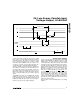
Bipolar Configuration
A -V
REFIN
to +V
REFIN
bipolar range is set up by con-
necting ROFS to REFIN and RFB to VOUT, and operat-
ing from dual (±5V) supplies (Figure 11). Table 5
shows the DAC-latch contents (input) vs. VOUT (out-
put). In this range, 1LSB = V
REFIN
(2
-9
).
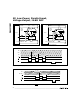
Four-Quadrant Multiplication
The MAX503 can be used as a four-quadrant multiplier
by connecting ROFS to REFIN and RFB to VOUT, and
using (1) an offset binary digital code, (2) bipolar
power supplies, and (3) a bipolar analog input at
REFIN within the range V
SS
+ 2V to V
DD
- 2V, as shown
in Figure 12.
In general, a 10-bit DAC’s output is D(V
REFIN
)(G),
where “G” is the gain (1 or 2) and “D” is the binary rep-
resentation of the digital input divided by 2
10
or 1,024.
This formula is precise for unipolar operation. However,
for bipolar, offset binary operation, the MSB is really a
polarity bit. No resolution is lost because the number of
steps is the same. The output voltage, however, has
been shifted from a range of, for example, 0V to
4.096V (G = 2) to a range of -2.048V to +2.048V.
Keep in mind that when using the DAC as a four-quad-
rant multiplier, the scale is skewed. The negative full
scale is -V
REFIN
, while the positive full scale is
+V
REFIN
- 1LSB.
* Write 10-bit data words with two sub-LSB 0s because the
DAC input latch is 12 bits wide.
* Write 10-bit data words with two sub-LSB 0s because the
DAC input latch is 12 bits wide.
* Write 10-bit data words with two sub-LSB 0s because the
DAC input latch is 12 bits wide.