
Datasheet


MAX5025–MAX5028
500kHz, 36V Output, SOT23,
Step-Up DC-DC Converters
_______________________________________________________________________________________ 9
where V
REF
is 1.25V
Determining Peak Inductor Current
If the boost converter remains in the discontinuous
mode of operation, then the approximate peak inductor
current, I
LPEAK
, is represented by the formula below:
where T
S
is the period, V
OUT
is the output voltage, V
IN
is the input voltage, I
OUT
is the output current, and η is
the efficiency of the boost converter.
Determining the Inductor Value
47µH is the recommended inductor value when the out-
put voltage is 30V and the input voltage is 5V. In gener-
al, the inductor should have a current rating greater
than the current-limit value. For example, the inductor’s
current rating should be greater than 150mA to support
a 4mA output current. Equivalent series resistance
(ESR) should be below 1Ω for reasonable efficiency.
Due to the MAX5025–MAX5028’s high switching fre-
quency, inductors with a ferrite core or equivalent are
recommended. Powdered iron cores are not recom-
mended due to their high losses at frequencies over
500kHz. Table 1 shows a list of vendors and 47µH
inductor parts.
For 4mA output current and output voltages other than
30V, the inductor can be simply scaled in value
according to the following formula:
Use the following formula to calculate the upper bound
of the inductor value at different output voltages and
output currents. This is the maximum inductance value
for discontinuous mode operation.
Calculate the lower bound, L
LOWER
, for the acceptable
inductance value using the following formula, which will
allow the maximum output current to be delivered with-
out reaching the peak current limit:
Notice that the switch current limit, (V
IN
/5)(260mA), is a
function of the input voltage, V
IN
. The current rating of
the inductor should be greater than the switch current
limit.
L
TV VI
V
mA
LOWER
S OUT IN OUT
IN
=
−
()
()
⎛
⎝
⎜
⎞
⎠
⎟
2
5
260
2
η
L
VV VT
IV
UPPER
OUT IN S
OUT OUT
IN
=
−
()
2
2
2
η
L
HV V
V
OUT IN
=
()
−
()
()
47
25
μ
I
TV VI
L
LPEAK
S OUT IN OUT
=
−
()
2
η
RR
V
V
OUT
REF
12 1=
⎛
⎝
⎜
⎞
⎠
⎟
-
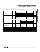
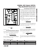
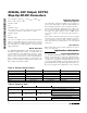
CONTROL
LOGIC
MAIN PWM
COMPARATOR
CURRENT-
LIMIT
COMPARATOR
FB
REF
-A
+A
+C
-C
MAX5025
MAX5026
THERMAL
SHUTDOWN
OSCILLATORULVO
PGND
3
GND
2
V
CC
5
SHDN
4
1
6LX
N
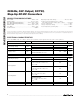
Table 1. Inductor Vendors
VENDOR PHONE FAX PART NUMBER OF 47µH INDUCTOR
Coilcraft 847-639-6400 847-639-1469 DT1608C-473
Sumida 847-545-6700 847-545-6720 CDRH4D28-470
Toko 847-297-0070 847-699-7864 A915BY-470M
Figure 1. Functional Diagram