
Datasheet


MAX4800A/MAX4802A
Low-Charge-Injection, 8-Channel, High-Voltage
Analog Switches with 20MHz Serial Interface
______________________________________________________________________________________ 11
Applications Information
Logic Levels
The devices’ digital interface inputs CLK, DIN, LE, and
CLR are tolerant of up to +6V, independent of the V
DD
supply voltage, allowing compatibility with higher volt-
age controllers.
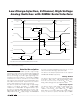
Daisy Chaining Multiple Devices
Digital output DOUT is provided to allow the connection
of multiple devices by daisy-chaining (Figure 3).
Connect each DOUT to the DIN of the subsequent
device in the chain. Connect CLK, LE, and CLR inputs
of all devices, and drive LE logic-low to update all
devices simultaneously. Drive CLR high to open all the
switches simultaneously. Additional shift registers may
be included anywhere in series with the MAX4800A/
MAX4802A data chain.
Supply Sequencing and Bypassing
The devices do not require special sequencing of the
V
DD
, V
PP
, and V
NN
supply voltages; however, analog
switch inputs must be unconnected, or satisfy V
NN
≤
(V
COM_
, V
NO_
) ≤ V
PP
during power-up and power-
down. Bypass V
DD
, V
NN
, and V
PP
to GND with a 0.1µF
ceramic capacitor as close to the device as possible.
Chip Information
PROCESS: BCDMOS
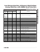
Table 1. Serial Interface Programming
X = Don’t care.
DATA BITS CONTROL BITS FUNCTION
D0
(LSB)
D1 D2 D3 D4 D5 D6
D7
(MSB)
LE
CLR
SW0 SW1 SW2 SW3 SW4 SW5 SW6
SW7
LLLOff
HLLOn
LLLOff
HLLOn
LLLOff
HLLOn
LLLOff
HLLOn
LLL Off
HLL On
LLL Off
HLL On
LLL Off
HLL On
LL L Off
HL L On
X X X X X X X X H L Hold Previous State
X X X X X X X X X H Off Off Off Off Off Off Off Off