
Datasheet


MAX4674
3V/5V, 4Ω, Wideband Quad
2:1 Analog Multiplexer
6 _______________________________________________________________________________________
Detailed Description
The MAX4674 is a low on-resistance (R
ON
), low-volt-
age, quad 2:1 analog multiplexer/demultiplexer that
operates from a +1.8V to +5.5V single supply. The
MAX4674 features very fast switching speed (t
ON
=
18ns max, t
OFF
= 6ns max) and guaranteed break-
before-make switching. Its low R
ON
allows high continu-
ous currents to be switched in a variety of applications.
Digital Interface
A0 and EN are CMOS digital inputs that meet TTL logic
levels when V+ = 5V. Note that A0 and EN can exceed
the voltage at V+ to a maximum of +5.5V. This feature
allows operation of the MAX4674 from a +3.3V supply
while controlling it with 5V CMOS logic signals.
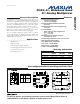
The Pin Configuration/Functional Diagram/Truth Table
located on the first page of this data sheet details the
operation of the MAX4674.
Applications Information
Power-Supply Considerations
Overview
The MAX4674 construction is typical of most CMOS
analog switches. It has two supply pins, V+ and GND,
used to drive the internal CMOS switches and set the
limits of the analog voltage on any switches. Reverse
ESD-protection diodes are internally connected
between each analog-signal pin and both V+ and
GND. If any analog signal exceeds V+ and GND, one
of these diodes conducts. During normal operation,
these and other reverse-biased ESD diodes leak, form-
ing the only current drawn from V
CC
or GND.
Virtually all the analog leakage current comes from the
ESD diodes. Although the ESD diodes on a given sig-
nal pin are identical and therefore fairly well balanced,
they are reverse biased differently. Each is biased by
either V+ or GND and the analog signal. This means
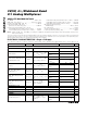
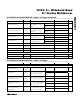
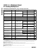
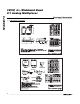
Pin Description
PIN
QSOP/TSSOP/SO
20 QFN 16 QFN
NAME
FUNCTION
1 20 15 A0 Address Input
2 1 16 NC1 Normally Closed Terminal
3 2 1 NO1 Normally Open Terminal
432
COM1
Analog Switch Common Terminal
5 4 3 NC2 Normally Closed Terminal
6 5 4 NO2 Normally Open Terminal
765
COM2
Analog Switch Common Terminal
—
7, 9, 17, 19
— N.C. No Connection
8 8 6 GND Ground
9107
COM3
Analog Switch Common Terminal
10 11 8 NO3 Normally Open Terminal
11 12 9 NC3 Normally Closed Terminal
12 13 10
COM4
Analog Switch Common Terminal
13 14 11 NO4 Normally Open Terminal
14 15 12 NC4 Normally Closed Terminal
15 16 13 EN Output Enable, Active Low
16 18 14 V+ Positive Supply Voltage
— EP EP EP Exposed Pad. Connect to GND.