
Datasheet

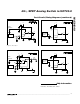

Pin Description
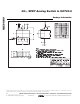
PIN NAME FUNCTION
1 COM Analog Switch Common
2 NC Normally Closed Switch Terminal. NC is connected to COM when IN is low.
3 GND Ground
4 V+ Positive Supply Voltage Input
5 N.C. No Connection
6 IN Digital Control Input
7 V- Negative Supply Voltage Input
8 NO Normally Open Switch Terminal. NO is connected to COM when IN is high.
MAX4649
Detailed Description
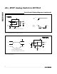
The MAX4649 is a high-voltage, single-pole/double-
throw (SPDT) analog switch that operates from dual
±4.5V to ±20V supplies or from a single +9V to +36V
supply. The MAX4649 has one normally closed (NC)
switch and one normally open (NO) switch. CMOS
switch construction allows bidirectional processing of
rail-to-rail analog signals.
The MAX4649 has break-before-make switching. The
transition time for switching from one input to the other
is typically 90ns. The off-leakage is typically less than
10pA, and on-leakage is typically less than 20pA.
Applications Information
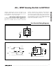
Overvoltage Protection
Proper power-supply sequencing is recommended for
all CMOS devices. Do not exceed the absolute maxi-
mum ratings, because stresses beyond the listed rat-
ings can cause permanent damage to the devices.
Always sequence V+ on first, then V-, followed by the
logic inputs, NO_, or COM. If power-supply sequenc-
ing is not possible, add two small signal diodes (D1,
D2) in series with supply pins (Figure 1). Adding
diodes reduces the analog signal range to one diode
drop below V+ and one diode drop above V-, but does
not affect the device’s low switch resistance and low
45Ω, SPDT Analog Switch in SOT23-8
6 _______________________________________________________________________________________
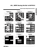
Typical Operating Characteristics (continued)
(T
A
= +25°C, unless otherwise noted.)
0.000001
0.0001
0.00001
0.1
0.01
0.001
1
10
100
1000
0231 456 78910111213
SUPPLY CURRENT
vs. LOGIC VOLTAGE
MAX4649 toc10
IN (V)
I+ (µA)
14 15
V+ = +15V
V- = -15V
-40
-30
-20
-10
0
10
20
30
40
-15 -5-10 0 5 10 15
CHARGE INJECTION
vs. V
COM
MAX4649 toc11
V
COM
(V)
CHARGE (pC)
A: V+ = +15V, V- = -15V
B: V+ = +12V, V- = 0
A
B
0
1.5
1.0
0.5
2.0
2.5
3.0
3.5
4.0
4.5
5.0
01020 30
LOGIC THRESHOLD
vs. SUPPLY VOLTAGE
MAX4649 toc12
V+ (V)
LOGIC THRESHOLD (V)