
Datasheet


MAX4571–MAX4574
Serially Controlled, Clickless
Audio/Video Switches
14 ______________________________________________________________________________________
SCLK
DIN
DOUT
t
CSS
t
CL
t
CH
t
CSW
t
CSO
t
DO
t
CSH
t
DH
t
DS
D15
D14
D1 D0
CS
20%
20% 20% 20% 20% 20%
20%
70%
70%
70%
70%
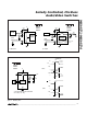
Figure 5. 3-Wire Serial-Interface Timing Diagram
SCLK
DIN
CS
LSB FROM
PREVIOUS WRITE
MSB FROM
PREVIOUS WRITE
COMMAND
EXECUTED
9
Q15........
MSB
D15 D14 D13....
.........00
8
16
1
DOUT
LSB
D1D2 D0....
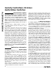
Figure 6. A Complete 3-Wire Serial-Interface Transmission
isters by connecting DOUT of the first device to DIN of
the second, etc. Connect the CS pins of all devices
together. Data are shifted through the MAX4573/
MAX4574s in series. When CS is brought high, all
devices are updated simultaneously. If any of the
devices in the chain are to be left unchanged, use a
NO_OP command for that device, as shown in Table 1.
An alternate way of connecting multiple devices is to
decode the CS line. In this case the DOUT pin is not
used and the DIN pins of all devices are connected
together. Address decode logic individually controls the
CS line of each device. When a device is to be selected
its CS line is brought low, data are shifted in, and its CS
is then brought high to execute the command.