
Datasheet


MAX4571–MAX4574
Serially Controlled, Clickless
Audio/Video Switches
______________________________________________________________________________________ 11
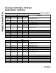
Table 1. Command Bit Mapping
Table 2. Data-Bit Switch Control
X = Don’t care
MSB MSB - 1 COMMAND DESCRIPTION
0 0 RESET Sets all switches open and in soft switching mode.
0 1 MODESET Sets specified switches to soft or hard mode.
1 0 NO_OP No Operation.
1 1 SWITCHSET Sets specified switches open or closed.
D13 X SW8
D12 X SW5
D11 X SW7B
D10 15, 16 SW7A
D8 19, 20 SW6A
X
X
X
SW11
SW9
15, 16
13, 14
17, 18
18, 19
21, 22
D7 21, 22 SW4B
D6 13, 14 SW4A
D5 11, 12 SW3B
D4 9, 10 SW3A
D3 7, 8 SW2B
SW8
SW7
SW6
SW5
SW4
11, 12
10, 11
8, 9
7, 8
5, 6
D2 5, 6 SW2A
D1 3, 4 SW1B
D0 (LSB) 1, 2 SW1A
SW3
SW2
SW1
4, 5
2, 3
1, 2
DATA BIT
SWITCHSWITCH
D9 17, 18 SW6BSW10 20, 21
SWITCH TERMINALS SWITCH TERMINALS
MAX4572/MAX4574MAX4571/MAX4573
communicating with the slave, it issues a stop condition
by transitioning SDA from low to high while SCL is high.
The bus is then free for another transmission.
3-Wire Serial Interface
The MAX4573/MAX4574 use a 3-wire SPI/QSPI/
MICROWIRE-compatible serial interface. An active-low
chip-select pin, CS, enables the device to receive data
from the serial input pin, DIN. Command and data infor-
mation are clocked in on the rising edge of the serial-
clock signal (SCLK) MSB first. A total of 16 bits are
needed in each write cycle. The write cycle allows two
8-bit-wide transfers if CS remains low for the entire 16
bits. The command code is contained in the two MSBs
of the 16-bit word. The remaining bits control the
switches as shown in Table 4. While shifting in the seri-
al data, the device remains in its original configuration.
A rising edge on CS latches the data into the
MAX4573/MAX4574 internal registers, initiating the
device’s change of state. Table 4 shows the details of
the 3-wire interface data structure.
Figures 5 and 6 and the
I/O Interface Characteristics
show the timing details of the 3-wire interface. If the
two command bits initiate a SWITCHSET command, a
logic 1 in a switch control location closes the associat-
ed switch, while a logic 0 opens it. If the command bits
initiate a MODESET command, a logic 1 in a switch
control location sets the associated switch into hard
mode, while a logic 0 sets it into soft, “clickless” mode.
For command-bit configurations, see Table 1.
Using Multiple Devices
There are two ways to connect multiple devices to the
same 3-wire serial interface. The first involves using the
DOUT pin. DOUT presents a copy of the last bit of the
internal shift register, useful for daisy-chaining multiple
devices. Data at DOUT are simply the input data
delayed by 16 clock cycles, appearing synchronous
with SCLK’s falling edge. After CS goes high, DOUT
holds the last bit in the shift register until new data are
shifted into DIN. For a simple interface using several
MAX4573/MAX4574 devices, daisy-chain the shift reg-