
Datasheet


The resistor improves the circuit’s phase margin by isolat-
ing the load capacitor from the op amp’s output.
Power-Up and Shutdown Modes
The MAX4231/MAX4233 have a shutdown option. When
the shutdown pin (SHDN) is pulled low, supply current
drops to 0.5μA per amplifier (V
DD
= 2.7V), the amplifiers
are disabled, and their outputs are driven to V
SS
. Since
the outputs are actively driven to V
SS
in shutdown, any
pullup resistor on the output causes a current drain from
the supply. Pulling SHDN high enables the amplifier. In
the dual MAX4233, the two amplifiers shut down indepen-
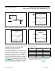
dently. Figure 10 shows the MAX4231’s output voltage
to a shutdown pulse. The MAX4231–MAX4234 typically
settle within 5μs after power-up. Figures 11 and 12 show
IDD to a shutdown plus and voltage power-up cycle.
When exiting shutdown, there is a 6μs delay before the
amplifier’s output becomes active (Figure 10).
Figure 9. Capacitive-Load-Driving Circuit Figure 11. Shutdown Enable/Disable Supply Current
Figure 10. Shutdown Output Voltage Enable/Disable Figure 12. Power-Up/Down Supply Current
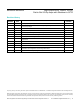
PART
AMPS PER
PACKAGE
SHUTDOWN
MODE
MAX4230
Single
—
MAX4231
Single Yes
MAX4232
Dual
—
MAX4233
Dual Yes
MAX4234
Quad
—
R
ISO
C
L
100µs/div
SHDN
2V/div
I
DD
1mA/div
OUT
2V/div
4µs/div
1V/div
1V/div
40µs/div
V
DD
2V/div
I
DD
1mA/div
MAX4230–MAX4234 High-Output-Drive, 10MHz, 10V/μs,
Rail-to-Rail I/O Op Amps with Shutdown in SC70
www.maximintegrated.com
Maxim Integrated
│
12
Selector Guide