
Datasheet


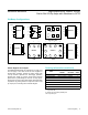


To improve step response when R′ > 2kΩ, connect small
capacitor Cf between the inverting input and output.
Choose Cf as follows:
C
f
= 8(R/R
f
) [pf]
where R
f
is the feedback resistor and R is the gain-setting
resistor (Figure 5).
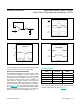
Driving Capacitive Loads
The MAX4230–MAX4234 have a high tolerance for
capacitive loads. They are stable with capacitive loads up
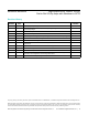
to 780pF. Figure 6 is a graph of the stable operating region
for various capacitive loads vs. resistive loads.Figures 7
and 8 show the transient response with excessive capaci-
tive loads (1500pF), with and without the addition of an
isolation resistor in series with the output. Figure 9 shows
a typical noninverting capacitive-load-driving circuit in the
unity-gain configuration.
Figure 6. Capacitive-Load Stability
Figure 7. Small-Signal Transient Response with Excessive
Capacitive Load
Figure 8. Small-Signal Transient Response with Excessive
Capacitive Load with Isolation Resistor
Figure 5. Inverting and Noninverting Amplifiers with Feedback
Compensation
0
500
1500
1000
2000
2500
1 10010 1k 10k 100k
RESISTIVE LOAD (Ω)
CAPACITIVE LOAD (pF)
V
DD
= 5.0V
R
L
TO V
DD
/2
STABLE
UNSTABLE
1µ/div
20mV/div
20mV/div
V
DD
= 3.0V, C
L
= 1500pF
R
L
= 100kΩ, R
ISO
= 0Ω
1µ/div
20mV/div
20mV/div
V
DD
= 3.0V, C
L
= 1500pF
R
L
= 100kΩ, R
ISO
= 39Ω
MAX4230
V
IN
V
OUT
R’ = R || R
f
R
f
C
f
= RC
IN
R
f
C
f
R
INVERTING
MAX4230
V
IN
V
OUT
R’ = R || R
f
R
f
C
f
= RC
IN
R
f
R
C
f
NONINVERTING
MAX4230–MAX4234 High-Output-Drive, 10MHz, 10V/μs,
Rail-to-Rail I/O Op Amps with Shutdown in SC70
www.maximintegrated.com
Maxim Integrated
│
11