
Datasheet


MAX3980
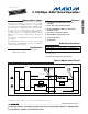
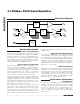
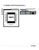
3.125Gbps XAUI Quad Equalizer
_______________________________________________________________________________________ 5
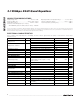
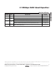
Pin Description
PIN NAME FUNCTION
1, 5, 9, 13,
23, 27, 31,
35
V
CC
+3.3V Supply Voltage
2 IN1+ Positive Equalizer Input Channel 1, CML
3 IN1- Negative Equalizer Input Channel 1, CML
4, 8, 12, 16,
26, 30, 34,
38
GND Supply Ground
6 IN2+ Positive Equalizer Input Channel 2, CML
7 IN2- Negative Equalizer Input Channel 2, CML
10 IN3+ Positive Equalizer Input Channel 3, CML
11 IN3- Negative Equalizer Input Channel 3, CML
14 IN4+ Positive Equalizer Input Channel 4, CML
15 IN4- Negative Equalizer Input Channel 4, CML
17–22, 39–42 N.C. No Connection. Leave unconnected.
24 OUT4- Negative Equalizer Output Channel 4, CML
25 OUT4+ Positive Equalizer Output Channel 4, CML
28 OUT3- Negative Equalizer Output Channel 3, CML
29 OUT3+ Positive Equalizer Output Channel 3, CML
32 OUT2- Negative Equalizer Output Channel 2, CML
33 OUT2+ Positive Equalizer Output Channel 2, CML
36 OUT1- Negative Equalizer Output Channel 1, CML
37 OUT1+ Positive Equalizer Output Channel 1, CML
43 EN
Enable Equalizer Input. A TTL high selects normal operation. A TTL low selects low-power
standby mode.
44 SDET Signal Detect Output for Channel 1. Produces a TTL high output when a signal is detected.
— EP
Exposed Pad. The exposed pad must be soldered to the circuit board ground plane for proper
thermal and electrical performance.