
Datasheet


MAX3863
the output-enable must be true to enable bias and
modulation currents.
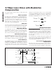
APC Loop Enable
The APC loop is enabled when an external capacitor is
placed between the APCFILT1 and APCFILT2 pins.
This capacitor sets the time constant of the APC loop.
To open the APC loop, the APCFILT1 pin is shorted to
ground. This shorts the feedback from the monitor
diode and causes the bias current to rise to the maxi-
mum value set by the BIASMAX pin.
APC Filter
The APC loop keeps the average optical power from the
laser constant. An external filter capacitor is used to stabi-
lize the APC loop. The typical capacitor value is 0.01µF.
APC Failure Monitor
The MAX3863 provides an APC failure monitor
(TTL/CMOS) to indicate an APC loop tracking failure.
FAIL is set low when the APC loop cannot adjust the
bias current to maintain the desired monitor current.
Short-Circuit Protection
The MAX3863 provides short-circuit protection for mod-
ulation, bias, and monitor current sources. If BIASMAX,
MODSET, or APCSET is shorted to ground, the bias
and modulation output are turned off and FAIL is active.
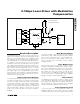
Current Monitors
The MAX3863 features monitor outputs for bias current
(BIASMON), modulation current (MODMON), and moni-
tor diode current (MDMON). The monitors are realized
by mirroring a fraction of the current and developing a
voltage across an external resistor. For the specified
voltage to monitor diode current, use an external 4kΩ
resistor at the MDMON output. Resistors for BIASMON
and MODMON are 100Ω. The minimum voltage at the
BIASMON and MODMON must be 2.1V for compliance.
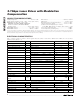
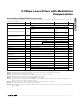
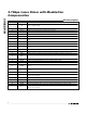
Design Procedure
When designing a laser transmitter, the optical output is
usually expressed in terms of average power and
extinction ratio. Table 1 shows relationships helpful in
converting between the optical average power and the
modulation current. These relationships are valid only if
the mark density and duty cycle of the optical wave-
form are 50%.
For a desired laser average optical power (P
AVG
) and
optical extinction ratio (r
e
), the required modulation cur-
rent can be calculated based on the laser slope effi-
ciency (η) using the equations in Table 1.
Laser Current Compensation
Requirements
Determine static bias and modulation current require-
ments from the laser threshold current and slope efficien-
cy. To use the APC loop with modulation compensation,
V
I
k
MDMON
MD
=×
4
4 Ω
VV
I
MODMON CC
MOD
=×−
45
100Ω
VV
I
BIASMON CC
BIAS
=×−
40
100Ω
2.7Gbps Laser Driver with Modulation
Compensation
8 _______________________________________________________________________________________
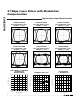
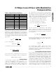
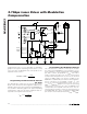
CLK+
CLK-
DATA+
I
MOD
DATA-
7mA TO 80mA
t
SU
t
HD
V
ID
= 0.2V
P-P
TO 1.6V
P-P
V
IS
= 0.1V TO 0.8V
V
IS
= 0.1V TO 0.8V
(DATA+) - (DATA-)
Figure 2. Required Input Signal, Setup/Hold-Time Definition and Output Polarity