
Datasheet


Applications Information
Layout Considerations
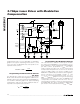
To minimize loss and crosstalk, keep connections
between the MAX3863 output and the laser diode as
short as possible. Use good high-frequency layout
techniques and multilayer boards with uninterrupted
ground plane to minimize EMI and crosstalk. Circuit
boards should be made using low-loss dielectrics. Use
controlled-impedance lines for the clock and data
inputs, as well as the module output.
Laser Safety and IEC 825
Using the MAX3863 laser driver alone does not ensure
that a transmitter design is compliant with IEC825. The
entire transmitter circuit and component selections
must be considered. Determine the level of fault toler-
ance required by each application and recognize that
Maxim products are not designed or authorized for use
as components in systems intended for surgical im-
plant into the body, for applications intended to support
or sustain life, or for any other application where the
failure of a Maxim product could create a situation
where personal injury or death may occur.
Exposed Pad Package
The exposed pad on the 32-pin QFN provides a very
low thermal resistive path for heat removal from the IC.
The pad is also electrical ground on the MAX3863 and
must be soldered to the circuit board ground for proper
thermal and electrical performance. Refer to Application
Note 862:
HFAN-08.1: Thermal Considerations of QFN
and Other Exposed-Paddle Packages
for additional
information.
II KI
I
V
R
K
R
MOD MODS BIAS
MODS
MODSET
MODCOMP
=+×
=×
=×
+
200
12
200
5
500
.
MAX3863
2.7Gbps Laser Driver with Modulation
Compensation
______________________________________________________________________________________ 11
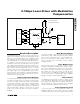
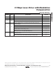
P1
LASER
POWER
T1 T2
P
AVG
I
BIAS1
I
BIAS2
I
MOD2
I
MOD1
P0
LASER CURRENT
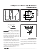
Figure 4. Laser Power vs. Current for a Change in Temperature
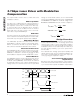
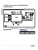
V
CC
50Ω
50Ω
DATA+
DATA-
GND
Figure 5. Equivalent Input Circuit
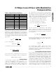
V
CC
I
MOD
MOD MODN GND
GND
Figure 6. Equivalent Output Circuit