
Datasheet


MAX3863
programming resistor. See the I
BIASMAX
vs. R
BIASMAX
graph in the
Typical Operating Characteristics
, and
select the value of R
BIASMAX
that corresponds to the
required current at +25°C.
Programming the Monitor Diode Current
Set Point
The APCSET pin controls the set point for the monitor
diode current. An internal current regulator establishes the
APCSET current in the same manner as the BIASMAX pin.
See the I
MD
vs. R
APCSET
graph in the
Typical Operating
Characteristics
, and select the value of R
APCSET
that cor-
responds to the required current at +25°C.
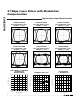
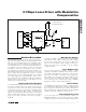
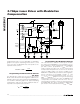
Programming the Modulation Current
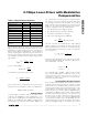
Two current sources combine to make up the modula-
tion current of the MAX3863 as seen in Figure 3. A con-
stant modulation current programmed at the MODSET
pin and a current, proportional to I
BIAS
, that varies
under control by the APC loop. See the
Laser Current
Compensation Requirements
section for the desired
values for I
MODS
and K. The portion of I
MOD
set by
MODSET is established by an internal current regulator,
which maintains the bandgap voltage of 1.2V
across the external programming resistor. See the I
MOD
vs. R
MODSET
graph in the
Typical Operating
Characteristics
and select the value of R
MODSET
that
corresponds to the required current at +25°C. The cur-
rent proportional to I
BIAS
is set by an external resistor at
the MODCOMP pin. Open circuiting the MODCOMP
pin can turn off the interaction between I
BIAS
and I
MOD
.
I
V
R
MD
APCSET
=×5
12.
I
V
R
BIASMAX
BIASMAX
=×200
12.
2.7Gbps Laser Driver with Modulation
Compensation
10 ______________________________________________________________________________________
V
CC
25Ω
V
CC
R
D
C
D
I
MOD
MOD
MODN
500pF
RTEN
x5
∑
I
BIAS
V
CC
C
APC
I
MD
I
MODS
I
MODC
V
bg
V
bg
+
-
V
bg
V
CC
V
CC
R
APCSET
x200
5Ω
BIAS
APCFILT1
APCFILT2
MD
x200
CURRENT
MONITOR
R
BIASMAX
R
MODCOMP
R
MODSET
MUX
DATA
DATA
CLK
CLK
BIASMON
MODMON
MDMON
EN
1
0
DQ
D
Figure 3. Functional Diagram