
Datasheet


MAX3480EA/MAX3480EB
±15kV ESD-Protected, Isolated, 3.3V
RS-485/RS-422 Data Interfaces
8 _______________________________________________________________________________________
Note: For DE
´
and DI
´
pin descriptions, see Detailed Block Diagram.
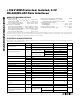
_________________________________________________Pin Description (continued)
PIN NAME FUNCTION
PINS ON THE ISOLATED RS-485/RS-422 SIDE
15
ISO RO
LED
Isolated Receiver-Output LED Anode (Input). If A > B by 200mV, ISO RO LED is high; if A < B by
200mV, ISO RO LED is low.
16
ISO COM2
Isolated-Supply Common Input. Connect to ISO COM1.
17
ISO DE
DRV
Isolated Driver-Enable Drive Input. The driver outputs, A and B, are enabled by bringing DE´ high.
The driver outputs are high impedance when DE´ is low. If the driver outputs are enabled, the
device functions as a line driver. While the driver outputs are high impedance, the device functions
as a line receiver. Open collector output; must have pullup (R4 in Figure 1) to ISO VCC and be
connected to ISO DE IN for normal operation (Table 1).
18
ISO V
CC2
Isolated-Supply Positive Input Voltage. Connect to ISO V
CC1
.
19
ISO DI DRV
Isolated Driver-Input Drive. With DE´ high, a low on DI´ forces output A low and output B high.
Similarly, a high on DI´ forces output A high and output B low. Open-collector output; must have
pullup (R5 in Figure 1) to ISO VCC and be connected to ISO DI IN for normal operation (Table 1).
20
ISO COM1
Isolated-Supply Common Output. Connect to ISO COM2. If RS-485 wires have a shield, connect
ISO COM1 to shield through 100Ω resistor.
21
ISO DE IN
Isolated Driver-Enable Input. Connect to ISO DE DRV for normal operation.
22
ISO DI IN
Isolated Driver Input. Connect to ISO DI DRV for normal operation.
23 A Noninverting Driver Output and Noninverting Receiver Input
24
ISO RO DRV
Isolated Receiver-Output Drive. Connect to ISO RO LED through R6 (Table 1 and Figure 1).
25 B Inverting Driver Output and Inverting Receiver Input
26
ISO V
CC1
Isolated Supply Positive Output Voltage. Connect to ISO V
CC2
.
27, 28
AC2, AC1
Internal Connections. Leave these pins unconnected.