
Datasheet


MAX3480EA/MAX3480EB
±15kV ESD-Protected, Isolated, 3.3V
RS-485/RS-422 Data Interfaces
12 ______________________________________________________________________________________
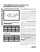
Figure 8. Receiver Propagation Delays
V
OH
V
OL
V
ID
-V
ID
1.5V
0
1.5V
OUTPUT
INPUT
0
RO
V
B
- V
A
t
PLH
t
PHL
t
SKD
= |t
PLH
- t
PHL
|
__Switching Waveforms (continued)
Function Tables
Table 2. Transmitting
INPUTS
DE´ DI´
B A
1 1 0 1
1 0 1 0
0 X
High
Impedance
High
Impedance
INPUTS OUTPUT
DE´
A-B
–
R
—
O
–
0 ≥ +0.2V 0
0 ≤ -0.2V 1
0 Inputs open 0
OUTPUTS
Table 3. Receiving
X = Don’t care.
The MAX3480EA/MAX3480EB withstand 1260V
RMS
(1 min) or 1560V
RMS
(1s). The isolated outputs of these
devices meet all RS-485/RS-422 specifications.
Boost Voltage
The MAX3480EA/MAX3480EB require external diodes
on the primary of the transformer to develop the boost
voltage for the power oscillator. In normal operation,
whenever one of the oscillator outputs (D1 and D2)
goes low, the other goes to approximately double the
supply voltage. Since the circuit is symmetrical, the two
outputs can be combined with diodes, filtered, and
used to power the oscillator itself.
The diodes on the primary side may be any fast-switch-
ing, small-signal diodes, such as the 1N914, 1N4148,
or CMPD2838. The nominal value of the primary filter
capacitor C3 is 0.01µF.
Driver Output Protection
There are two mechanisms to prevent excessive output
current and power dissipation caused by faults or by
bus contention. A foldback current limit on the output
stage provides immediate protection against short cir-
cuits over the whole common-mode voltage range (see
the Typical Operating Characteristics). In addition, a
thermal shutdown circuit forces the driver outputs into
a high-impedance state if the die temperature rises
excessively.
Resistor R8 (Figures 1 and 2) provides additional pro-
tection by current limiting between the shield and the
two signal wires. In the event that shielded cable is
used and an external voltage or transient is inadver-
tently applied between the shield and the signal wires,
the MAX3480EA/MAX3480EB can be damaged.
Although unlikely, this condition can occur during
installation.
The MAX3480EA/MAX3480EB provide electrical iso-
lation between logic ground and signal paths; they
do not provide isolation from external shields and
the signal paths. When in doubt, do not connect the
shield. The MAX3480EA/MAX3480EB can be dam-
aged if resistor R8 is shorted out.
Applications Information
The MAX3480EA/MAX3480EB provide extra protection
against ESD. The MAX3480EA/MAX3480EB are intend-
ed for harsh environments where high-speed commu-
nication is important. These devices eliminate the
need for transient suppressor diodes or the use of
discrete protection components. The standard (non-E)
MAX3480A/MAX3480B are recommended for applica-
tions where cost is critical.