
Datasheet
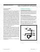


In general, a transmitter’s rise time relates directly to the
length of an unterminated stub, which can be driven with
only minor waveform reflections. The following equation
expresses this relationship conservatively:
Length = t
RISE
/(10 x 1.5ns/ft)
where t
RISE
is the transmitter’s rise time.
For example, the MAX3442E’s rise time is typically 800ns,
which results in excellent waveforms with a stub length up
to 53ft. A system can work well with longer unterminat-
ed stubs, even with severe reflections, if the waveform
settles out before the UART samples them.
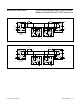
RS-485 Applications
The MAX3440E–MAX3443E transceivers provide
bidirectional data communications on multipoint bus
transmission lines. Figures 13 and 14 show a typical
network applications circuit. The RS-485 standard covers
line lengths up to 4000ft. To minimize reflections and
reduce data errors, terminate the signal line at both ends
in its characteristic impedance, and keep stub lengths off
the main line as short as possible.
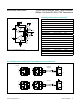
J1708 Applications
The MAX3444E is designed for J1708 applications. To
configure the MAX3444E, connect DE and RE to GND.
Connect the signal to be transmitted to TXD. Terminate
the bus with the load circuit as shown in Figure 15. The
drivers used by SAE J1708 are used in a dominant-mode
application. DE is active low; a high input on DE
places the outputs in high impedance. When the driver is
disabled (TXD high or DE high), the bus is pulled high
by external bias resistors R1 and R2. Therefore, a logic
level high is encoded as recessive. When all transceivers
are idle in this configuration, all receivers output logic
high because of the pullup resistor on A and pulldown
resistor on B. R1 and R2 provide the bias for the reces-
sive state. C1 and C2 combine to form a 6MHz lowpass
filter, effective for reducing FM interference. R2, C1, R4,
and C2 combine to form a 1.6MHz lowpass filter, effective
for reducing AM interference. Because the bus is untermi-
nated, at high frequencies, R3 and R4 perform a pseudo-
termination. This makes the implementation more flexible,
as no specific termination nodes are required at the ends
of the bus.
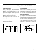
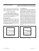
Figure 12. Driver Output Waveform and FFT Plot of
MAX3442E Transmitting a 125kHz Signal
Figure 11. Driver Output Waveform and FFT Plot of
MAX3443E Transmitting a 125kHz Signal
5.00MHz500kHz/div0
20dB/div
2V/div
5.00MHz500kHz/div0
20dB/div
2V/div
www.maximintegrated.com
Maxim Integrated
│
15
MAX3440E–MAX3444E ±15kV ESD-Protected, ±60V Fault-Protected,
10Mbps, Fail-Safe RS-485/J1708 Transceivers