
Datasheet


MAX3362
3.3V, High-Speed, RS-485/RS-422 Transceiver in
SOT Package
4 _______________________________________________________________________________________
Note 1: Devices production tested at +25°C. Over-temperature limits are guaranteed by design.
Note 2: All currents into the device are positive; all currents out of the device are negative. All voltages are referenced to device
ground, unless otherwise noted.
Note 3: ΔV
OD
and ΔV
OC
are the changes in V
OD
and V
OC
, respectively, when the DI input changes state.
Note 4: The short-circuit output current applies to peak current just prior to foldback-current limiting; the short-circuit foldback out-
put current applies during current limiting to allow a recovery from bus contention.
Note 5: Shutdown is enabled by bringing RE high and DE low. If the enable inputs are in this state for less than 50ns, the device is
guaranteed not to enter shutdown. If the enable inputs are in this state for at least 600ns, the device is guaranteed to have
entered shutdown.
Note 6: Transition time from shutdown mode to normal operation.
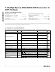
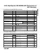
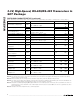
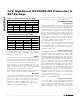
SWITCHING CHARACTERISTICS (continued)
(V
CC
= +3.3V ±5%, T
A
= T
MIN
to T
MAX
, unless otherwise noted. Typical values are at V
CC
= +3.3V and T
A
= +25°C.) (Note 1)
PARAMETER SYMBOL CONDITIONS MIN TYP MAX UNITS
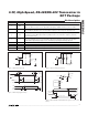
Driver Enable to Output High t
PDZH
Figure 5,
R
L
= 500Ω, C
L
= 50pF
100 ns
t
PRLH
50
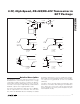
Receiver Propagation Delay
t
PRHL
Figure 6, C
L
= 15pF
50
ns
Receiver Output Skew t
RSKEW
Figure 6, C
L
= 15pF
t
RSKEW
= |t
PRLH
- t
PRHL
|
6ns
Receiver Enable to Output Low t
PRZL
Figure 7, R
L
= 1kΩ, C
L
= 15pF 100 ns
Receiver Enable to Output High t
PRZH
Figure 7, R
L
= 1kΩ, C
L
= 15pF 100 ns
Receiver Disable Time from Low t
PRLZ
Figure 7, R
L
= 1kΩ, C
L
= 15pF 100 ns
Receiver Disable Time from
High
t
PRHZ
Figure 7, R
L
= 1kΩ, C
L
= 15pF 100 ns
Time to Shutdown t
SD
(Note 5) 50 600 ns
Driver Enable from Output High
to Shutdown
t
PDHS
50 600 ns
Driver Enable from Output Low
to Shutdown
t
PDLS
50 600 ns
Receiver Enable from Output
High to Shutdown
t
PRHS
50 600 ns
Receiver Enable from Output
Low to Shutdown
t
PRLS
50 600 ns
Time to Normal Operation t
NO
(Note 6) 1500 3000 ns
Driver Enable from Shutdown to
Output High
t
PDSH
Figure 5
R
L
= 500Ω, C
L
= 50pF
1500 3000 ns
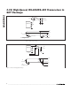
Driver Enable from Shutdown to
Output Low
t
PDSL
Figure 4
R
L
= 500Ω, C
L
= 50pF
1500 3000 ns
Receiver Enable from Shutdown
to Output High
t
PRSH
Figure 7
R
L
= 1kΩ, C
L
= 15pF
1500 3000 ns
Receiver Enable from Shutdown
to Output Low
t
PRSL
Figure 7
R
L
= 1kΩ, C
L
= 15pF
1500 3000 ns