
Datasheet


Setting the Preemphasis Interval
The MAX3291 has an internal fixed preemphasis interval
of 100ns. Use the MAX3291 for existing designs requiring
industry-standard ’75180 pin-compatibility at data rates of
5Mbps to 10Mbps.
The MAX3292 has a resistor-programmable preemphasis
interval for more flexibility. For data rates less than 1Mbps,
use the following equation to calculate R
PSET
(the pre-
emphasis setting resistor):
R
PSET
= 580 (t
BAUD
- 100)
where t
BAUD
= one baud period in ns.
For example, a baud rate of 500kbps produces a baud
period of 2µs (2µs = 2000ns).
R
PSET
= 580 (t
BAUD
- 100)
R
PSET
= 580 (2000 - 100) = 1.1MΩ
For data rates of 1Mbps to 10Mbps, use the following
equation to calculate R
PSET
:
R
PSET
= 580 (t
BAUD
- 100)(t
BAUD
/ 1000)
where t
BAUD
= one baud period in ns.
For example, a baud rate of 1Mbps produces a baud
period of 1µs (1µs = 1000ns).
R
PSET
= 580 (1000 - 100)(1000 / 1000) = 522kΩ
(closest standard value is 523kΩ)
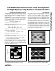
Set the preemphasis interval by connecting the R
PSET
resistor from PSET to V
CC
. Use a 0.1µF bypass capaci-
tor (C
PSET
) from PSET to V
CC
. If PSET is connected
directly to V
CC
(R
PSET
= 0), the preemphasis interval
reverts to the nominal 100ns value.
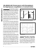
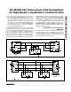
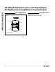
Eye Diagrams
One simple method to quickly determine your circuit
configuration is to view an eye diagram. An eye dia-
gram is a scope photo (voltage vs. time) showing the
transitions of a pseudo-random bit string displaying at
least one bit interval. Use an eye diagram to quickly
calculate the total jitter of a circuit configuration. Jitter is
the total time variation at the zero-volt differential cross-
ing, and percent jitter is expressed as a percentage of
one baud period, t
BAUD
. Figures 15 and 16 show typi-
cal eye diagrams for a non-preemphasis device and
the MAX3291/MAX3292. ISI and jitter are often used
interchangeably; however, they are not exactly the
same thing. ISI usually makes up the majority of the jit-
ter, but asymmetrical high and low driver output voltage
levels and time skews of non-ideal transceivers (driver
and receiver) also contribute to jitter.
MAX3291/MAX3292
RS-485/RS-422 Transceivers with Preemphasis
for High-Speed, Long-Distance Communication
______________________________________________________________________________________ 11
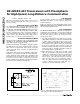
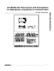
10,000
100
0.1 1 10
DATA RATE (Mbps)
CABLE LENGTH (FEET)
1000
10% JITTER
PREEMPHASIS
485 DRIVER
LIMIT
CONVENTIONAL
485 DRIVER
LIMIT
PREEMPHASIS REQUIRED
FOR ERROR-FREE
TRANSMISSION
24-GAUGE
TWISTED PAIR
Figure 14. Preemphasis Driver Performance Compared to a
Conventional Driver Without Preemphasis at 10% Jitter
Figure 15. Eye Diagram of a Typical RS-485 Transceiver
Without Preemphasis, while Driving 1000 feet of Cable at
5Mbps
Figure 16. Eye Diagram of the MAX3292 with a Preemphasis
Interval of 175ns, while Driving 1000 feet of Cable at 5Mbps