
Datasheet


MAX31865
RTD-to-Digital Converter
8Maxim Integrated
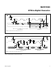
Pin Description (continued)
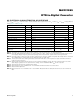
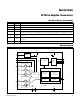
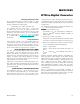
Block Diagram
PIN NAME FUNCTION
15 DGND Digital Ground
16 GND1 Analog Ground. Connect to GND2.
17 N.C. Do Not Connect
18
DRDY
Active-Low Push-Pull Data-Ready Output. DRDY goes low when a new conversion result is available in
the data register. When a read-operation of an RTD resistance data register occurs, DRDY returns high.
19 DVDD
Digital Supply Voltage Input. Connect to a 3.3V power supply. Bypass to DGND with a 0.1FF bypass
capacitor.
20 V
DD
Analog Supply Voltage Input. Connect to a 3.3V power supply. Bypass to GND1 with a 0.1FF bypass
capacitor.
— EP Exposed Pad (Bottom Side of Package). Connect to GND1.
DATA REGISTERS
VBIAS
GENERATOR
DIGITAL LOGIC
SERIAL
LOGIC
BIAS
V
DD
V
DD
V
DVDD
REFIN+
REFIN-
ISENSOR
FORCE+
FORCE2
RTDIN+
FORCE-
RTDIN-
DVDD
SCLK
SDO
SDI
CS
DRDY
DGND
3-WIRE
ONLY
50/60Hz DIGITAL
SINC FILTER
ADC STATE
MACHINE
DIGITAL
COMPARATOR
FOR
FAULT DETECTION
MASTER-INITIATED
FAULT-DETECTION
CYCLE
15-BIT
Σ∆ ADC
MAX31865
GND1
±50V PROTECTION
GND2