
Datasheet


MAX3172/MAX3174
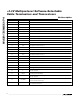
+3.3V Multiprotocol Software-Selectable
Cable Terminators and Transceivers
4 _______________________________________________________________________________________
ELECTRICAL CHARACTERISTICS (continued)
(V
CC
= +3.3V ± 5%, T
A
= T
MIN
to T
MAX
. Typical values are at V
CC
= +3.3V, T
A
= +25°C, unless otherwise noted. See Note 2 for V+
and V- input voltage conditions.)
PARAMETER SYMBOL CONDITIONS MIN TYP MAX UNITS
V.28 TRANSMITTER
R
L
= 3kΩ, Figure 3 ±5.0 ±5.4
Output Voltage Swing V
O
Open circuit, Figure 3 ±6.5
V
Short-Circuit Current I
SC
T4OUT = GND ±25 ±60 mA
MAX3172CAI
MAX3174CAI
430
R
L
= 3kΩ,
C
L
= 2500pF
measured from +3V
to -3V or -3V to +3V,
Figure 3
MAX3172EAI 3 30
Output Slew Rate SR
R
L
= 7kΩ , C
L
= 150pF measured from
+3V to -3V or -3V to +3V, Figure 3
630
V/µs
Transmitter Propagation Delay t
PHL
, t
PLH
1µs
Data Skew
| t
PHL
-
t
PLH
|
100 ns
V.28 RECEIVER
Input Threshold Low V
IL
1.1 0.8 V
Input Threshold High V
IH
2.0 1.6 V
Input Hysteresis V
HYS
0.5 V
MAX3172 5 10 15 µs
Receiver Propagation Delay t
PHL
, t
PLH
Figure 4
MAX3174 200 ns
MAX3172CAI 0.5 4
MAX3172EAI 0.5 5
µs
Data Skew
| t
PHL
-
t
PLH
|
Figure 4
MAX3174 100 ns
Note 2: The charge pump on the MAX3171/MAX3173 can supply V+ and V- to the MAX3172/MAX3174. The V+ and V- input levels
vary with the mode of chipset operation as follows:
V.35/V.28 modes: +5.55V ≤ V+ ≤ +6.50V, -6.50V ≤ V- ≤ -5.45V
Typical operation: V+ = +5.90V, V- = -5.80V
V.10/V.11 modes: +4.20V ≤ V+ ≤ +5.0V, -4.60V ≤ V- ≤ -3.80V
Typical operation: V+ = +4.60V, V- = -4.20V
The MAX3171/MAX3173 are guaranteed to provide these V+/V- supply levels.