
Datasheet


MAX3172/MAX3174
+3.3V Multiprotocol Software-Selectable
Cable Terminators and Transceivers
2 _______________________________________________________________________________________
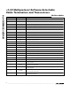
ABSOLUTE MAXIMUM RATINGS
ELECTRICAL CHARACTERISTICS
(V
CC
= +3.3V ± 5%, T
A
= T
MIN
to T
MAX
. Typical values are at V
CC
= +3.3V, T
A
= +25°C, unless otherwise noted. See Note 2 for V+
and V- input voltage conditions.)
Stresses beyond those listed under “Absolute Maximum Ratings” may cause permanent damage to the device. These are stress ratings only, and functional
operation of the device at these or any other conditions beyond those indicated in the operational sections of the specifications is not implied. Exposure to
absolute maximum rating conditions for extended periods may affect device reliability.
Note 1: V+ and V- can have maximum magnitudes of 7V, but their absolute difference cannot exceed 13V.
(All voltages referenced to GND unless otherwise noted.)
Supply Voltages
V
CC
......................................................................-0.3V to +4V
V+ (Note 1)..........................................................-0.3V to +7V
V- (Note 1) ...........................................................+0.3V to -7V
V+ to V- (Note 1) ...............................................................13V
Logic Input Voltages
M0, M1, M2, DCE/DTE, INVERT, T4IN ................-0.3V to +6V
Logic Output Voltages
R4OUT...................................................-0.3V to (V
CC
+ 0.3V)
Short-Circuit Duration............................................Continuous
Transmitter Outputs
T4OUT ................................................................-15V to +15V
Short-Circuit Duration ........................................................60s
Receiver Input
R4INA .................................................................-15V to +15V
Termination Network Inputs (applied individually)
R_A, R_B ............................................................-15V to +15V
Continuous Power Dissipation (T
A
= +70°C)
28-Pin SSOP (derate 9.52mW/°C above +70°C) ........762mW
Operating Temperature Range
MAX3172CAI/MAX3174CAI...............................0°C to +70°C
MAX3172EAI...................................................-40°C to +85°C
Junction Temperature......................................................+150°C
Storage Temperature Range .............................-65°C to +150°C
Lead Temperature (soldering, 10s) .................................+300°C
PARAMETER SYMBOL CONDITIONS MIN TYP MAX UNITS
DC CHARACTERISTICS
All modes V.10 receiver inactive 80 200
Supply Current
(Digital Inputs = GND or V
CC
)
I
CC
All modes V.10 receiver active 400 750
µA
No-cable mode
0.2 1.0
V.10/V.11/V.28/V.35 modes unloaded 0.5 2.5
V.10/V.11 modes T4OUT loaded 11.0 14.0
V+ Supply Current
(T4IN = GND)
I
V+
V.28/V.35 modes T4OUT loaded 3.0 5.0
mA
No-cable mode -0.4 -1.0
V.10/V.11/V.28/V.35 modes unloaded -0.8 -2.5
V.10/V.11 modes T4OUT loaded -11.0 -14.0
V- Supply Current
(T4IN = V
CC
)
I
V-
V.28/V.35 modes T4OUT loaded -3.0 -5.0
mA
TERMINATOR NETWORKS (R_A, R_B)
Differential-Mode Impedance
V.35 Mode
Figure 1, -2V ≤ V
CM
≤ +2V 90 104 110 Ω
Common-Mode Impedance
V.35 Mode
Figure 2, -2V ≤ V
CM
≤ +2V 135 153 165 Ω
Differential-Mode Impedance
V.11 Mode
Figure 1, -7V ≤ V
CM
≤ +7V 100 104 110 Ω
Network OFF Impedance I
Z
Switches open, -15V ≤ V
A
≤ +15V, V
B
= V
A
,
V
B
= GND or V
B
floating
50 150 kΩ
LOGIC INPUTS (M0, M1, M2, INVERT, DCE/DTE, T4IN)
Input High Voltage V
IH
2.0 V
Input Low Voltage V
IL
0.8 V
Logic Input Current I
IH
, I
IL
V
IN
= V
CC
or GND ±1 µA