
Datasheet


MAX3172/MAX3174
+3.3V Multiprotocol Software-Selectable
Cable Terminators and Transceivers
10 ______________________________________________________________________________________
networks are configured to provide 100Ω differential
impedance and 150Ω common-mode impedance to ter-
minate the MAX3170 V.35 transmitter outputs and receiv-
er inputs.
Termination Mode Selection
The mode-select pins M0, M1, M2, and DCE/DTE control
the state of the five termination networks (Table 1). The
mode-select table of the MAX3172/MAX3174 is compati-
ble with the MAX3170 mode-select table so that the M0,
M1, M2, and DCE/DTE pins can be connected to the cor-
responding pins on the MAX3170. For example, M2 = 1,
M1 = 0, M0 = 0 corresponds to V.35 mode for both the
MAX3172/MAX3174 and the MAX3170 clock/data trans-
ceiver chip.
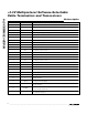
R4/T4 Mode Selection
The MAX3172/MAX3174 include a transceiver for use in
applications requiring an extra serial handshake signal
(for example, local loopback). The transceiver can be
PROTOCOL M2 M1 M0 DCE/DTE INVERT T4 R4
Not Used (Default V.11) 0 0 0 0 0 Z V.10
RS-530A 0 0 1 0 0 Z V.10
RS-530 0 1 0 0 0 Z V.10
X.21 0 1 1 0 0 Z V.10
V.35 1 0 0 0 0 Z V.28
RS-449/V.36 1 0 1 0 0 Z V.10
V.28/RS-232 1 1 0 0 0 Z V.28
No Cable 1 1 1 0 0 Z Z
Not Used (Default V.11) 0 0 0 1 0 V.10 Z
RS-530A 0 0 1 1 0 V.10 Z
RS-530 0 1 0 1 0 V.10 Z
X.21 0 1 1 1 0 V.10 Z
V.35 1 0 0 1 0 V.28 Z
RS-449/V.36 1 0 1 1 0 V.10 Z
V.28/RS-232 1 1 0 1 0 V.28 Z
No Cable 1 1 1 1 0 Z Z
Not Used (Default V.11) 0 0 0 0 1 V.10 Z
RS-530A 0 0 1 0 1 V.10 Z
RS-530 0 1 0 0 1 V.10 Z
X.21 0 1 1 0 1 V.10 Z
V.35 1 0 0 0 1 V.28 Z
RS-449/V.36 1 0 1 0 1 V.10 Z
V.28/RS-232 1 1 0 0 1 V.28 Z
No Cable 1 1 1 0 1 Z Z
Not Used (Default V.11) 0 0 0 1 1 Z V.10
RS-530A 0 0 1 1 1 Z V.10
RS-530 0 1 0 1 1 Z V.10
X.21 0 1 1 1 1 Z V.10
V.35 1 0 0 1 1 Z V.28
RS-449/V.36 1 0 1 1 1 Z V.10
V.28/RS-232 1 1 0 1 1 Z V.28
No Cable 1 1 1 1 1 Z Z
Table 3. R4/T4 Mode-Select Table