
Datasheet


MAX199
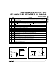
External Clock Mode
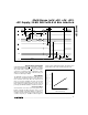
Select external clock mode by writing the control byte
with D7 = 0 and D6 = 0. Figure 8 shows CLK and WR
timing relationships in internal and external acquisition
modes, with an external clock. A 100kHz to 2.0MHz
external clock with 45% to 55% duty cycle is required
for proper operation. Operating at clock frequencies
lower than 100kHz will cause a voltage droop across
the hold capacitor, and subsequently degrade perfor-
mance.
Multi-Range (±4V, ±2V, +4V, +2V),
+5V Supply, 12-Bit DAS with 8+4 Bus Interface
12 ______________________________________________________________________________________
WR
CLK
CLK
WR
WR GOES HIGH WHEN CLK IS HIGH
WR GOES HIGH WHEN CLK IS LOW
t
CWS
t
CWH
ACQUISITION STARTS
ACQUISITION STARTS
CONVERSION STARTS
CONVERSION STARTS
ACQUISITION ENDS
ACQUISITION ENDS
ACQMOD = "0"
ACQMOD = "0"
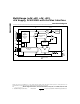
Figure 8a. External Clock and WR Timing (Internal Acquisition Mode)
WR
CLK
CLK
WR
WR GOES HIGH WHEN CLK IS HIGH
WR GOES HIGH WHEN CLK IS LOW
t
DH
t
DH
t
CWH
t
CWS
ACQUISITION STARTS
ACQUISITION STARTS
CONVERSION STARTS
CONVERSION STARTS
ACQUISITION ENDS
ACQUISITION ENDS
ACQMOD = "1"
ACQMOD = "1"
ACQMOD = "0"
ACQMOD = "0"
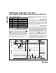
Figure 8b. External Clock and WR Timing (External Acquisition Mode)